|
SDS 300+300
600Watt Amp by Sandy Sims |
||
 |
||
|
SDS 300+300
600Watt Amp by Sandy Sims |
||
|
|
||
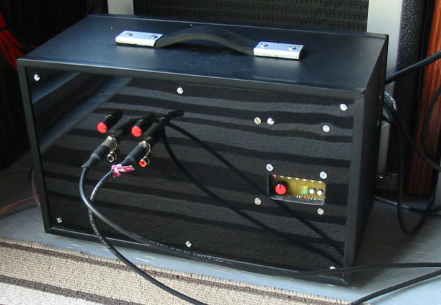
The amp shown above
is my newest pride & joy. It has a real 600 Watts to 8 ohms,
A fully programmable Quasi-12 band parametric EQ, MIDI controllability, a 15
page
EQ Memory, lights up pretty colors with the music, and sounds awesome!!
To see how it was built, read on!
|
A
new amp has been on the "wish list" for quite a while over here. So I went
to the Carvin site and picked out a nice little mixer/amp, about 350 Watts
total, and went to order it. My suspicious better half queried me, "Do you know what the shipping will be?" and I replied, "well the guy said $65 to Canada by UPS, but then taxes on top of that...." Wrong!! UPS, while adored in the USA, is a bad thing here as they do their own customs brokering, which they charge lots for, and then have their own add-on fees. So Gena contacted the fellow at Carvin, and asked if they could ship it US Post. Nope, he says, "it's too big." Ya right. Well UPS was going to charge us $210, which is 2/3 of the price of the amp so I went to plan B.
|
|
|
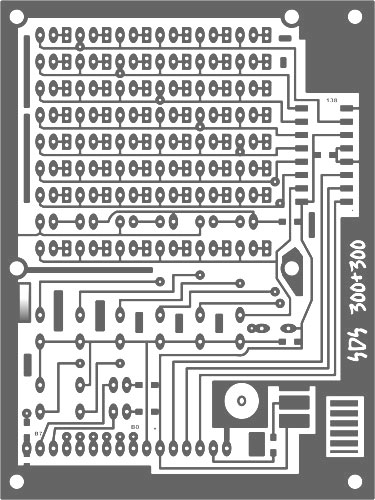
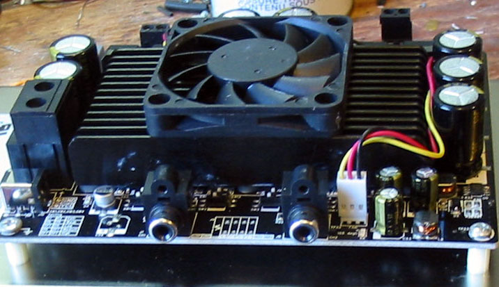
I
have been eyeballing several Chinese companies selling various amp boards
and power supplies to drive them. I ordered the 600 Watt amp board (right) ,
and a 48 Volt, 12.5 A power supply from Sure Electronics. That amperage is
nominal because it can draw up to 12 Amps on the 120VAC lines!
To make a long story short on those, I ended up just building another amp (they have all the schematics online!) as the main chip is a $15 part from Digikey. Most of the other stuff I already have, including heatsink & a fan. The project didn't end there, (of course!) as the main thing I wanted on the amp is some form of EQ. I found these lovely little audio chips from ST MicroElectronics, called the TDA7419. I've used a similar chip from them before when I built the micro-power stereo for the boat. Somehow I forgot
how cryptic the datasheets were. The ones for the 7419 are even worse! Pin
functions were omitted, so I had to stumble on to them, and the whole thing
was written in broken English so pretty hard to understand at all. |
 |
|
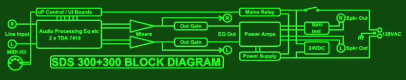
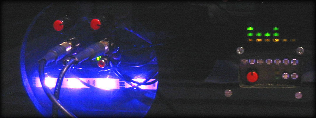
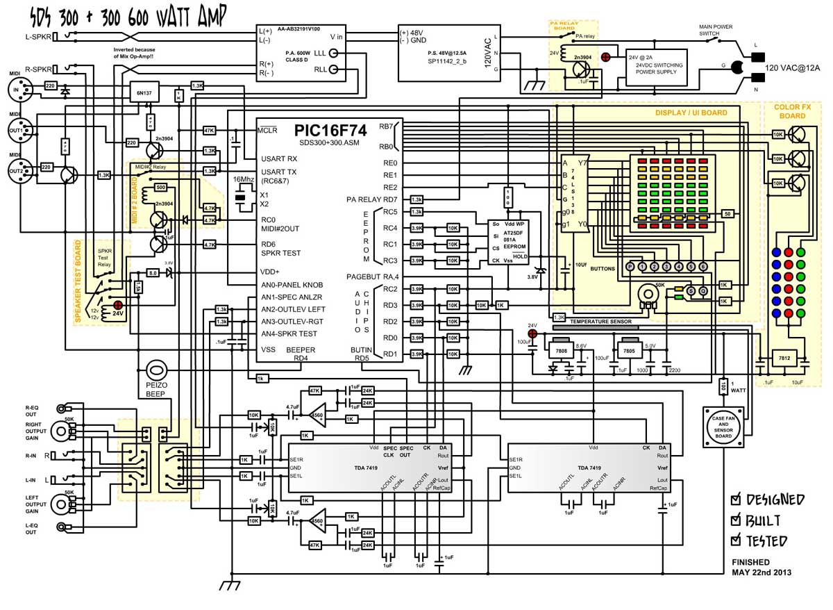
Below
is a basic block diagram of the whole thing. One reason I chose the TDA7419
is it has a spectrum analyzer on it, and I think it's something that's
missing on standard mixers/amps. It is a visual aide when tuning an EQ, or
at least to me it is. It gives a general idea of the audio coming in, which
tends towards the low end frequencies, and in a max-output scenario, pulling
up some of the higher bands can be important.
|
|
|
|
|
|
Anyway!
One drawback to the TAD7419's is they have only 3 bands. But each band can
be shifted 4 ways at will, plus the 2 lower bands have a "Quality Factor"
adjustment. This is really just a bandwidth selector, from wide to narrow.
There *is* a 4th band, the sub output, which could be mixed back into the
chip, but I chose not to use that as on stage, subs get lost unless they are
a massive "power-grid" size. The way I solved this band number problem was to use 2 chips, and mix them after. This gives a possible 12 bands plus Q-Factors. That's enough for a good stage amp. |
|||
|
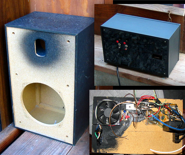
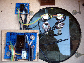
I
had some little speaker cases that I tore speakers out of for my battery
powered busking set-up, which I thought would make a nice case for the amp,
plus I'd have a spare it case I messed it up. My neighbor gave me some
plastic molding that just fit over the edges to protect them.
The power supply
has it's own fan (noisy too!) and the amp has a fan, but I thought I'd
better put a fan on the back and drill a hole in the bottom to allow air to
circulate out of the box. My other neighbor had given me some dark Plexiglas
sheets which really came in handy for doing the face. The back panel soon became really busy with the 3rd fan, audio sockets, MIDI sockets, relays, and a 24 Volt switching supply I found at the Economy Store for a buck. If I could do it again, I'd have substituted the back panel (old style press board crap) with 3/8" plywood....but with some epoxy re-enforcements and backing plates it seems strong enough. Well enough with the mechanical stuff, lets get on to the really interesting part, the electronics!
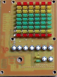
The two out-of-place lower buttons are for band shift, and Q-Factor, which work with the knob also. |
|
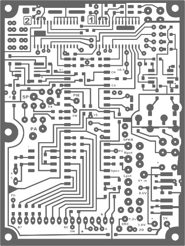
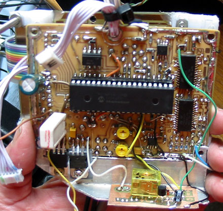
||
| This board is just the display board, the other being the processor board where all the action happens. I chose (yet again!) the PIC16F74, mostly because of the port count, and the built-in USART, but also because I know it so well, I can program it in my sleep. Also I can re-use routines I wrote long ago for similar interfaces. | |||
The PIC chip must perform the following functions to control the amp:
|
 |
||||||||||
 |
|||||||||||
|
The
AN0-4 on the PIC are configured as ADC's to read levels on the front panel
knobs (EQ, Left, Right) , the spectrum analyzer (SA) input, and Speaker
test levels. The SA is kind of weird in that it's output impedance is well over 100K, which is far beyond the PIC's max ADC recommendation, I slowed the ADC some in the program and it seems to work fine, which is a miracle really! The Main Output level pots are on AN 2&3. I used 50k pots, but this is ok as a .1uF cap makes up for the PIC's 10k ADC cap charge limitation. The speaker test input is basically a voltage test from a 1.2V source into a unknown speaker through an 8 ohm resistor. 8 ohms=.6V 4ohms=.4V (r1/r1+r2)*E
The LED display
also doubles as the button sampler. PortB is loaded with the LED bits
(high = on) and Port E selects the row it will be in through a 74LS138 3-8
demux. (Open collector outs) You may
have noticed there's a lot of 3.9K and 10K resistors coming off ports.
This is because of pain-in-the-butt 3.3V devices. I still cling to 5V
everything as a habit and a principle!
The
Voltages on the board are 5V, 8.6V, and 24V. The 24V comes from a
switching supply that comes on with the power switch, and is also used to
drive various relays and even the fan.
|
|||||||||||
|
The
time came (at last!) to put everything together and stuff it into the tiny
speaker box. It barely fit, but I managed to get the back on with *some* force hehe. I hooked up the speakers, and some inputs from my mixer board, flicked it on and everything worked, no smoke!!
I've never heard my tower speakers sound so good, ever. Finally they have
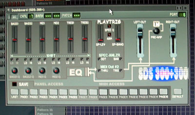
some "real" power to boom it out. Right away (while listening to a
somewhat loud DJKJ mix) I started to make a FL Studio Dashboard to test
the MIDI stuff. I played with it all afternoon then took it over to show off to the neighbors (as they contributed some stuff right?) I'm happy! Much better than just buying stuff. That said, I now have realized I need to pull it apart and fix / change / add a few things: 1) Flip the speaker +/- around! I forgot I had inverted the signal with the 4560 op-amps! 2)
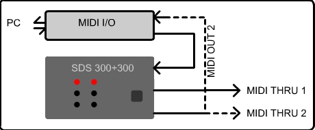
Make a MIDI-Thru "power off" bypass. Sometimes I want MIDI after the amp
without turning 3)
After making the "Dashboard" pictured above, I realized that when I change
an EQ page, the 4)
I want to add a MIDI-controlled "power-down" that will both power down
with a MIDI note 5)
Need to get some labels or lettering, this came out nicer than I thought
and using a paint pen
Well there you go! It was a bit of a hair puller, but it's my new baby,
and I'm sure it'll be There's a zip download below that includes the .asm, the owners manual and schematics + info.
Cheers! |

|
| May28 2013 | ||
|
Disclaimer: This is not an
instructional page to build or manufacture the above project, nor are there
any guarantees of accuracy herein. This page is an "of interest" discussion, and the project is intended for my own personal use. If you have any questions, or wish to pursue this project, you may contact me (Sandra) at fresh(at)freshnelly.com |
![]()