My
love of creating stuff and hauling it on stage will be piqued by this
section alone. If you read my project
A 600 Watt 2 Channel Amp
then just multiply that by 8. To clarify, I plan to use the TDA 7718, an
easy to use audio processor for
automotive use (this is portable right?) for each of 6 Channel strips. 2
strips will be mono and each have their own EQ, and 4 will be stereo, which
makes 10 channels. Then there's a post EQ, same chip, for post FX/Sampler/distortionPIC
(it became evident this would be required!) and the TDA 7415 monster
Multimedia processor for EQ and selection of the final outputs.
I have never used this exact chip, but I have used it's brother the TDA
7419, which also has a spectrum analyzer on it, except this one can be
switched to external input, thus each channel can be analyzed! Yay!
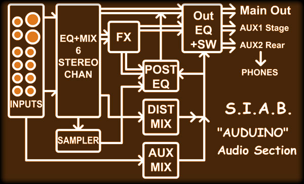
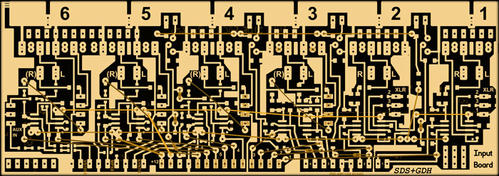
A really
basic layout of the audio section is shown to the right. The 6 pairs of
inputs are buffered with low noise amps, but channel 1,2 and 3L and 3R
have pre-amps.
Channel 1 and 2 (Mic and Guitar #1) have Single-ended (1/4" socket)
balanced (XLR socket) inputs. Channel 3L and 3R are just single ended
(secondary Mic and Guitar).
Channels 4 to 6 are stereo inputs from keyboards, external synths, drum
machine etc. These also have an internal mix with the built-in
mySynth II, MPX-8 Drum Sampler, and VS-1053 MIDI synth. These would be
used for smaller systems / stage setups.
The 6
MIDI-controllable EQ's fed by the buffers send adjustable levels to the
Main Output EQ, the FX Module, the distortionPIC module, and the
sampler. These levels can be set in any combination or muted. Branching
out these low noise signals makes this more like a mixer.
The FX,
distortionPIC, or Sampler can be selected into the Post EQ for
on-the-fly tone changes during a song, or just to fine tune that already
fine guitar distortion. Note that the FX, distortion, and Sampler can
all be fed directly to the Main Output EQ as well, but are phase
inverted compared to the post-EQ to add yet another dimension if used
together.
The AUX
MIX is a direct tap off of the inputs, before EQ's. This can be routed
to AUX1 or AUX2 Outputs direct for stage monitors or extra dimensional
sound (side/rear speakers) |
 |
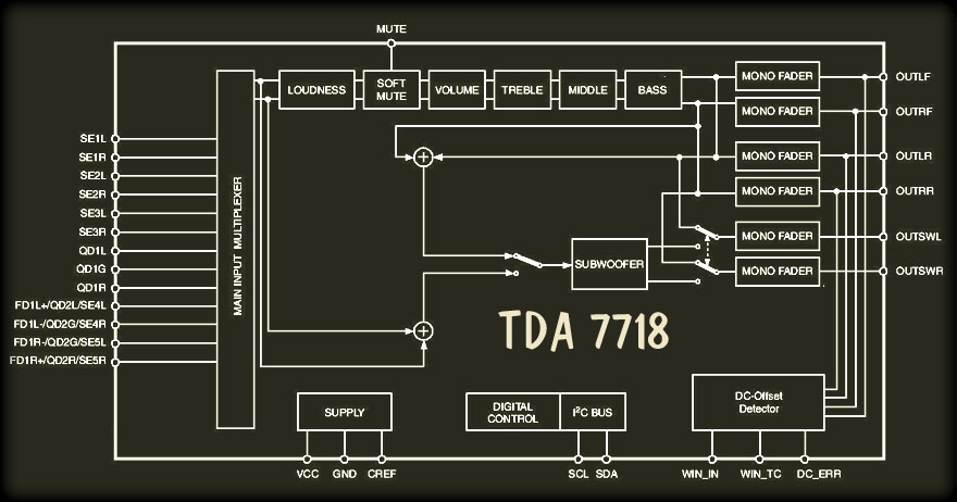
As you can
see, the 7718 has a set of filters for Treble, Middle, and Bass. Each one of
these have 4 frequency center settings, and Bass & Mid have 4 Q settings,
which is really all you need on a strip outside of the studio. A bonus to
this chip is that it has a mixed output meant for sub, but as
sub EQ can be set to flat, it can be used as a general purpose output.
(we'll see!)
There is also a mute pin, which I won't be using. I was thinking of a
separate monitor bus for the headphones, but I think I'll put them off the
TDA7419's OUTRL & OUTRR.
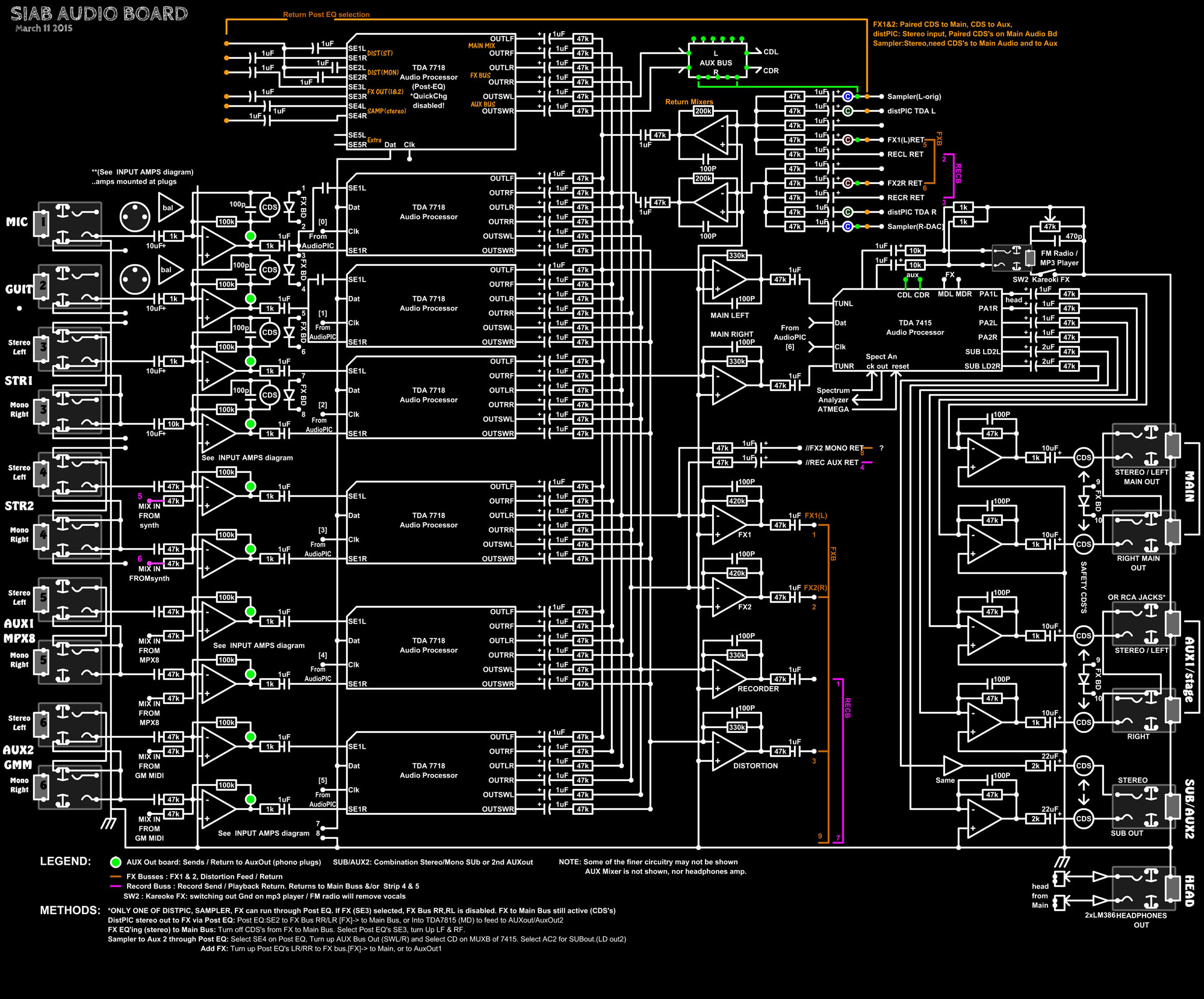
Without
further adieu, here's the basic audio diagram as it is May 2nd 2015:
|
|
Image
Updated May 2nd, 2015 Click to enlarge |
|
|
...This is pretty much the final design as the boards have been made!
(That's the only way to stop myself!)
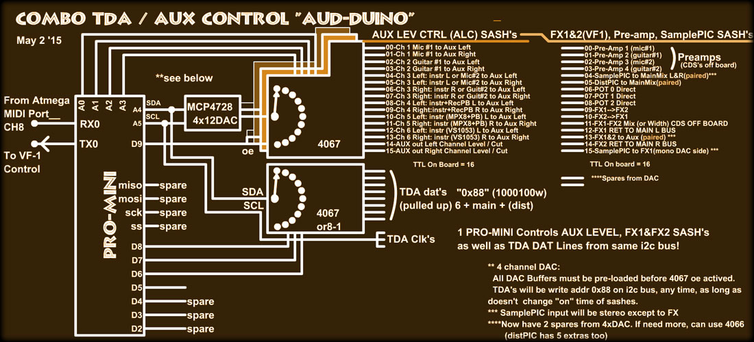
All
of the TDA chips are controlled by the tiny Arduino Pro-Mini I call
"Auduino" by way of using an analogue switch (low draw!) 4067 to switch in
the data line of the I2C interface. (Brown diagram below) I had to do this
as the TDA7718 address is not configurable, which is a shame really, as the
TDA7415 is different. Oh well!
The "Auduino" receives data by way of standard MIDI CC's on Channel (15) to
control the 100+ parameters in the TDA7718's then on the system MIDI channel
(16) the control data for the TDA7415 output driver, along with SASH data.
The ATMEGA (S.I.A.B. Main Control) sends this data derived from panel
controls, Presets, and MIDI Songs.
The
"Auduino" also must relay data to control the FV-1 FX board via it's USART
TX also on MIDI baud rate and standard MIDI CC's. If you haven't seen the FX
page, the FX board has an FV-1 DSP that is interfaced with a PIC
microcontroller to control/upload the different FX programs to the FV-1. To
allow remote updates of these FX programs (i.e. Reverb3, EchoFall,
PitchShift1) the "Auduino" must switch the PIC into RS-232 ASCII-HEX mode by
way of a MIDI SysEx. Because this is all on the same port as numerous other
periferals (mySynth, Sampler, LCD, distPIC) they must be checked for SysEx
response (I think only the Sampler will be an issue...ug!) See
FX page
for more on all that.
|
The first 2
channel strips have pre-amps as mentioned above, while the 3rd strip (STR
1) has a stereo pre-amp. This is for an additional gitter and mic should
someone want to play/sing along and didn't bring their own
"Show-in-a-box" lol! These pre-amps can be switched out and are variable
level like the first 2. Each of those 7718 inputs have an Input Volume
control from -31 dB to +23 dB, but for standard line-level inputs it
always stays at zero in my experience. The Volume control won't entirely
mute a signal, that's up to the speaker outputs if needed.
Hopefully things will stay relatively low noise. The LM-833 op amps
shown will be run on +/- 12 volts which helps, and I've to optimize
impedances. All of the TDA 7718 front/rear outputs feed into the Main
Mix op amps, and the FX 1 and/or FX 2. I thought this was kinda cool,
L-rear into FX2 and R-rear into FX1 as the FX input can be dual mono.
The FX "module" was to be PT2399's, but that's all changed to the
amazing FV-1. FX has it's own page
here.
The FX outputs go into the main mix as well as the Post EQ and/or the
Main EQ as just FX. This way, the FX can be output as it's own channels
(on MAIN or AUX2 or AUX1!) which I've tried before. This adds a whole
new dimension to the sound if "those" speakers are positioned well.
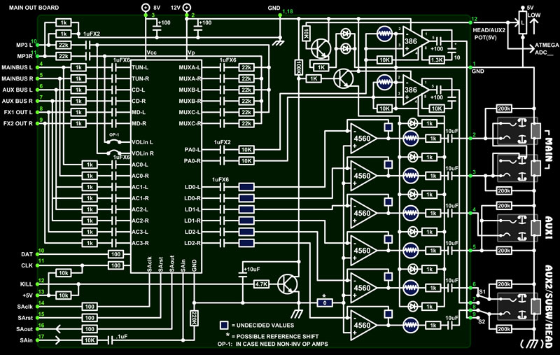
The final Mix is
ran through a TDA7415, which isn't LEVEL or EQ automated by a MIDI song, so
it can be tuned for the stage, and out into the world. If the world includes
a big subwoofer setup, the AUX2 can be configured to output sub frequencies
only, or a combination of sub and mono all band. The switches are to select
headphones on this socket.
|
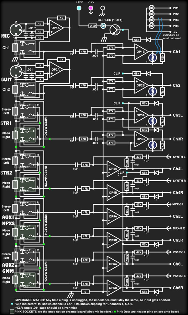
Input Section - Click
to enlarge
Note: 47K impedances
used to allow use of tiny 1uF SMD capacitors. Like my little
socket drawings? They are pin accurate and from EBay. |
|
There will be presets for these configurations on the output TDA-7415,
but the MIDI song playing will have little control. I've learned that
automation of everything is fine, as long as it isn't Main output
levels, or EQ settings! These need to be tuned to the stage and
Amp/speaker combination, not the song.
My diagram
simplifies the LQFP 64-pin TDA-7415 drastically, believe it or not, but
as this is a proto-type board, there were some questions not answered in
the datasheet. The OP-1 jumpers may require a dual op-amp board be added
for the MUX Mix. This input feeds to the EQ as does AC0L/R internally.
The bizarre transistor circuitry is a pot driven level control for the
headphones. The LEDs drive the CDS low which lowers the headphone input
level. The reason this has been done this way is because the same pot
doubles as the AUX2 level control when headphones aren't being used,
which is digital controlled by the ATMEGA Main processor, therefore
requiring (linear) 5V to 0V.
I know
this must all seem pretty complex, and I'm trying to melt it down into
something understandable (not my best skill) so please be patient. If
you read this page before, you may have noticed it's completely changed,
as will other pages of the project unless it warrants leaving on the
page for informative purposes. I promise that changes will be minimal
now that most of the boards have been made.
 |
|
|
The
diagram above is the new Sash boards configuration. The SASH circuit as
mentioned on the FX page
is my acronym for "Sample and Sorta Hold". When a voltage is presented
on the input ( to Base of first Q ) the small cap is charged to that
voltage. Then when the input is switched out to high impedance, the
Darlington Q arrangement holds the voltage (-1.2V) for a few seconds.
This voltage is in turn used to drive an LED through a 100-470 ohm
resistor (depending on output requirements) which illuminates a CDS
Photocell. This photocell resistance is then placed in the appropriate
part of an audio circuit.
I've
found this to be completely non-linear, especially at the lower voltage
levels, but it's guaranteed to isolate the audio from the digital.
Digital volume pots are quite good these days, but can sometimes cause
issues in high-gain stuff (like a pre-amp!) and are "clicky" in even the
most balanced of circuits.
There are ways around this, a "soft-step" circuit, but it's a lot of
extra parts and board space (I'd imagine) and likely more power
consumption.
|
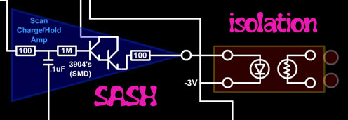
SASH circuit: -3V
is to offset loss of 1.2V in Q's and
voltage drop of white 602 SMD LED (>1.8V) |
|
Because the
MCP4728 DAC ( 4 output ) is 12 bits, the non-linearity can be totally
programmed out anyway, on a case by case basis if need be, using math
(x^y+offset) or tables. Only 2 DAC outputs are being used to drive 4067
the 32 SASHes via analog switches, so there's room for expansion if
needed. |
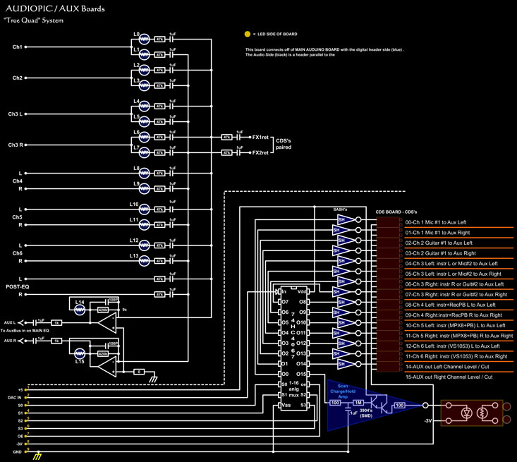 |
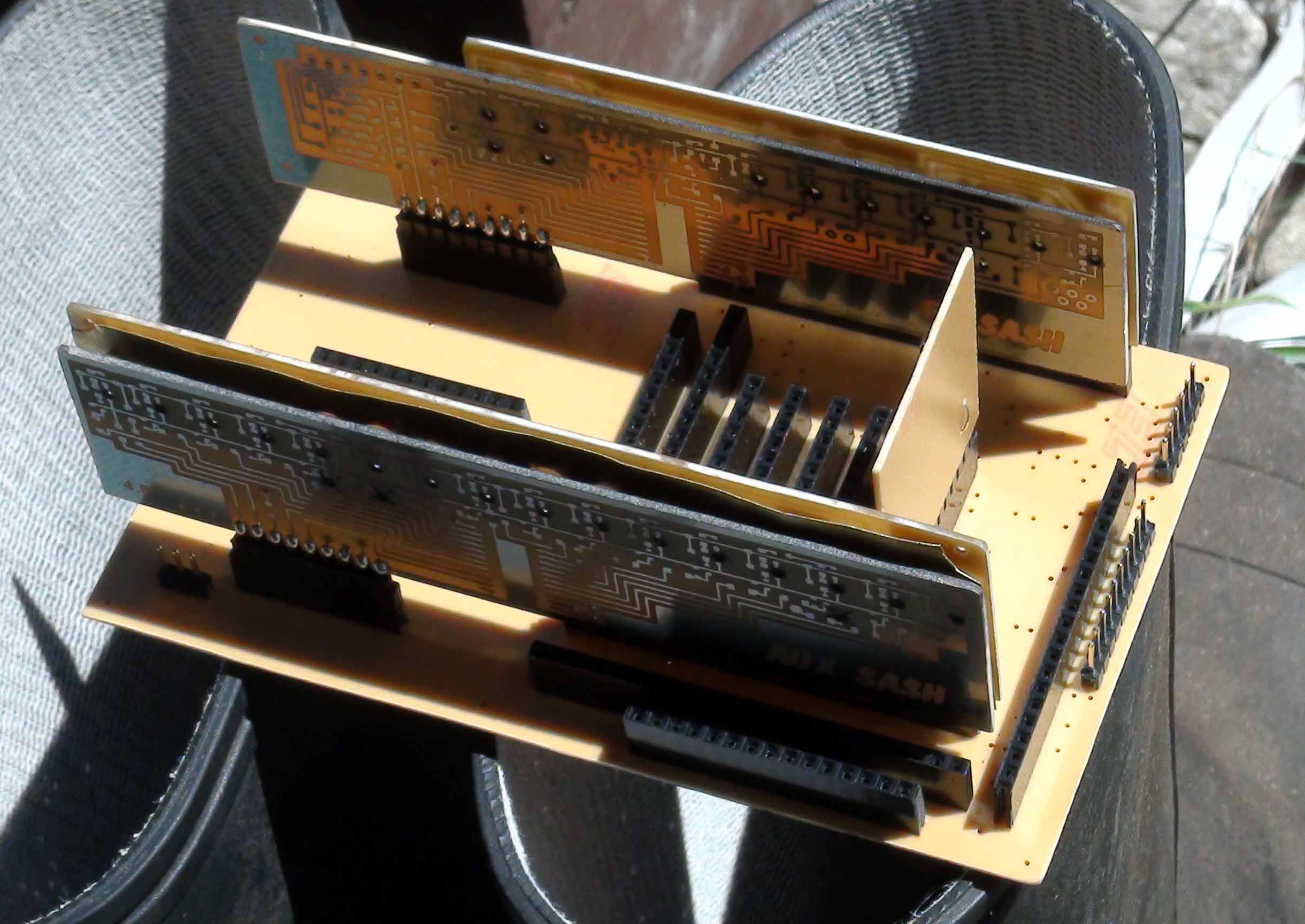
The 2 sets of
16 SASH controls are AUX IN and FX Return/Pre-Amps/FX1-FX2 feedback/FX
FV-1 Pots/Sampler & distortionPIC to mainbus feeds.
The AUX
IN just mixes any selected input channels to the Aux Bus, which is in
turn fed to the selected output(s). This is not to be confused with the
Aux Outs 1 & 2, although the Aux bus output can feed to those.
So
Audio that can be fed to the Aux Bus L and/or R includes:
Input Channels 1,2,3L,3R,4L,4R,5L,5R,6L,6R
Post (return) EQ output SWL/SWR [Sampler or distPIC or FX]
FX1 and FX2 returns (controlled by FX SASHes)
mySynth II L & R (Via mix to Channel 4)
MPX-8 Drum Sampler (Via mix to Channel 5)
VS-1053 GM MIDI Synth (Via mix the Channel 6)
That
all makes it pretty versatile me thinks! Here's a photo (below) off all
of the boards together (with a few parts on them). Appx 5 1/2" across.
|
Sometime
soon I'll post the boards, or at least images of them, not that anyone will
ever use them, they add to the explanation.
Well that's
it for June 2015! I must take a break over summer (sun tans, sailing,
swimming), but will be back on the project in the fall!
Here's a
bunch of images, just click to enlarge.
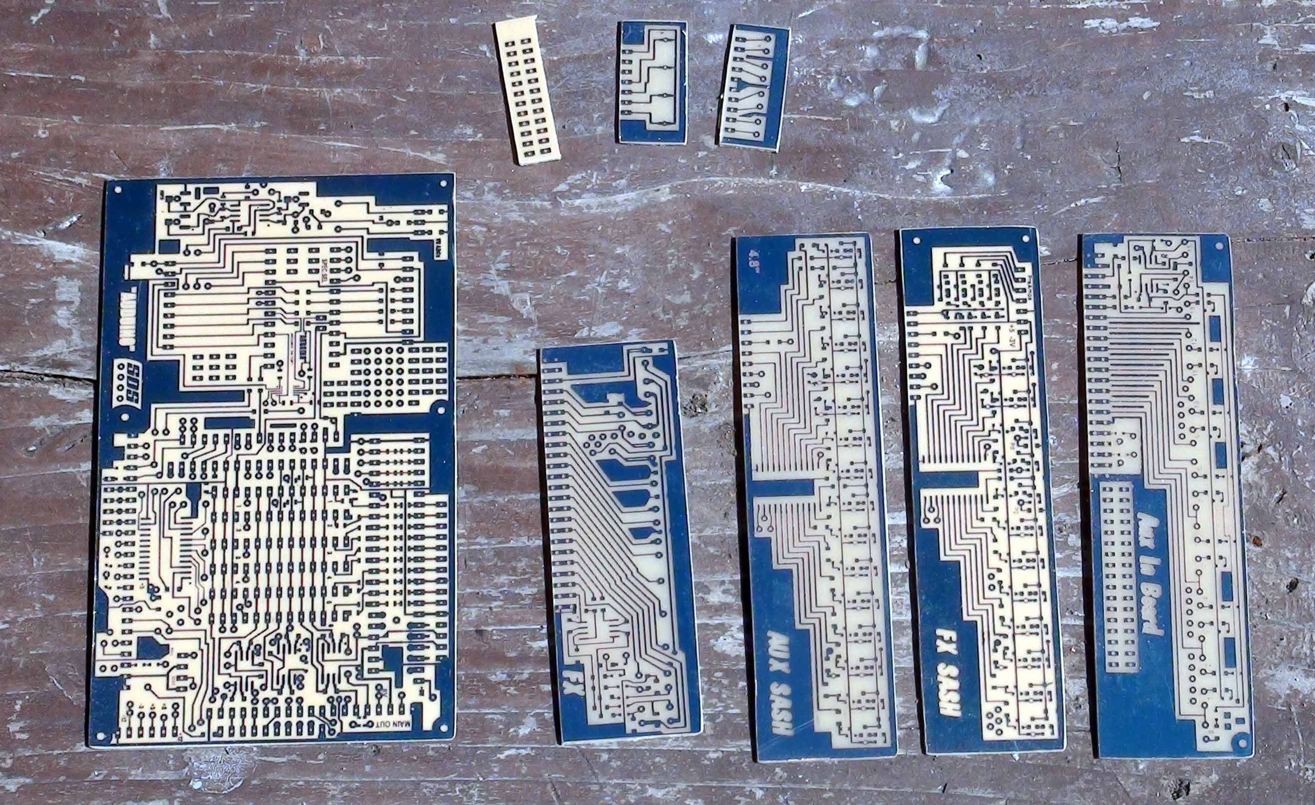
Some boards fresh
out of the etch
The tiny boards are for the pre-amp SASH/header for the front end input
amps / 1/4" sockets board (below) |
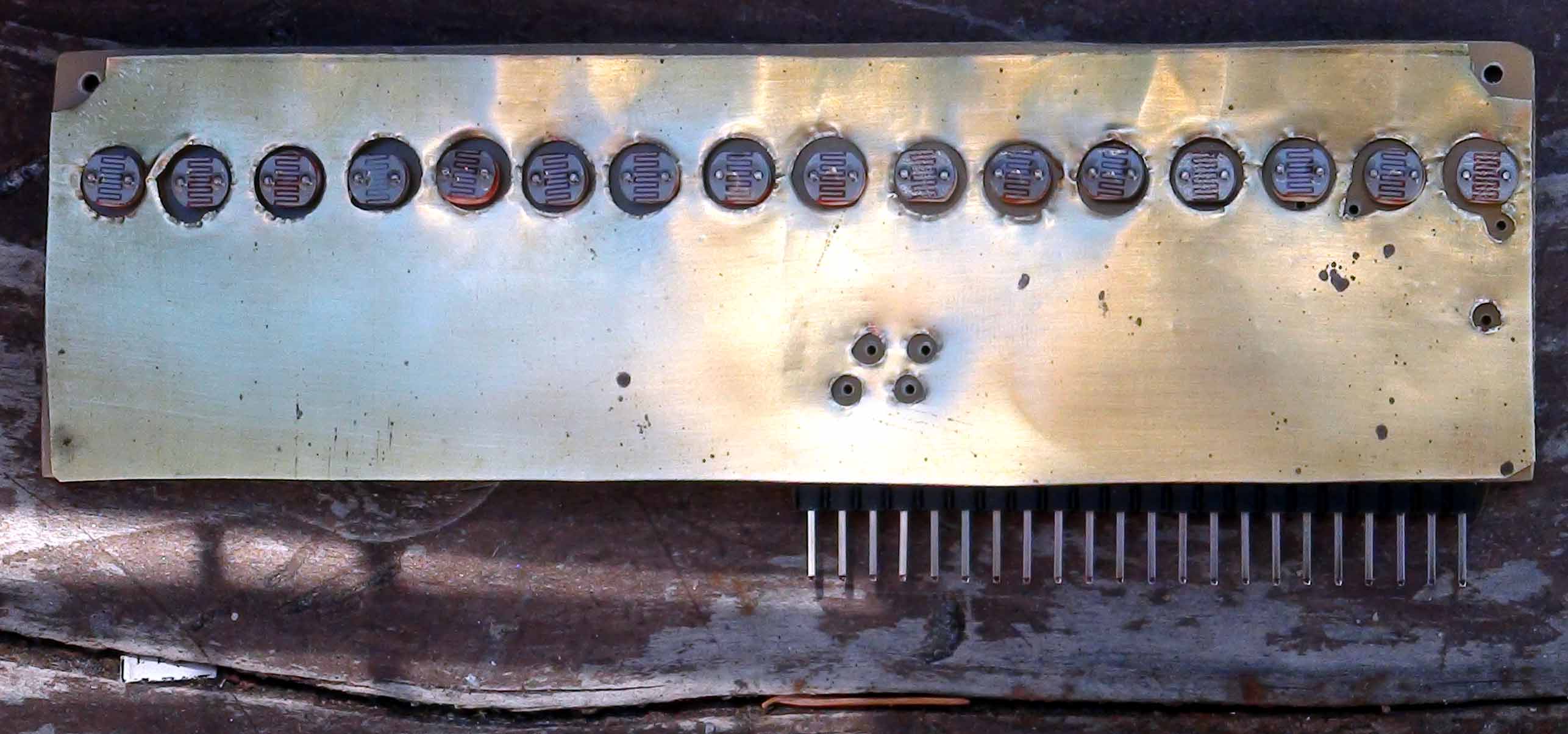
AUX board with
brass shielding
Blocks stray light from CDS (LDR's) , but also shields from surrounding
fields and gives a good ground plane. |
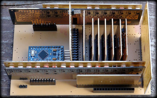
Partially
together.
The Audio Out board and remaining TDA boards to go |
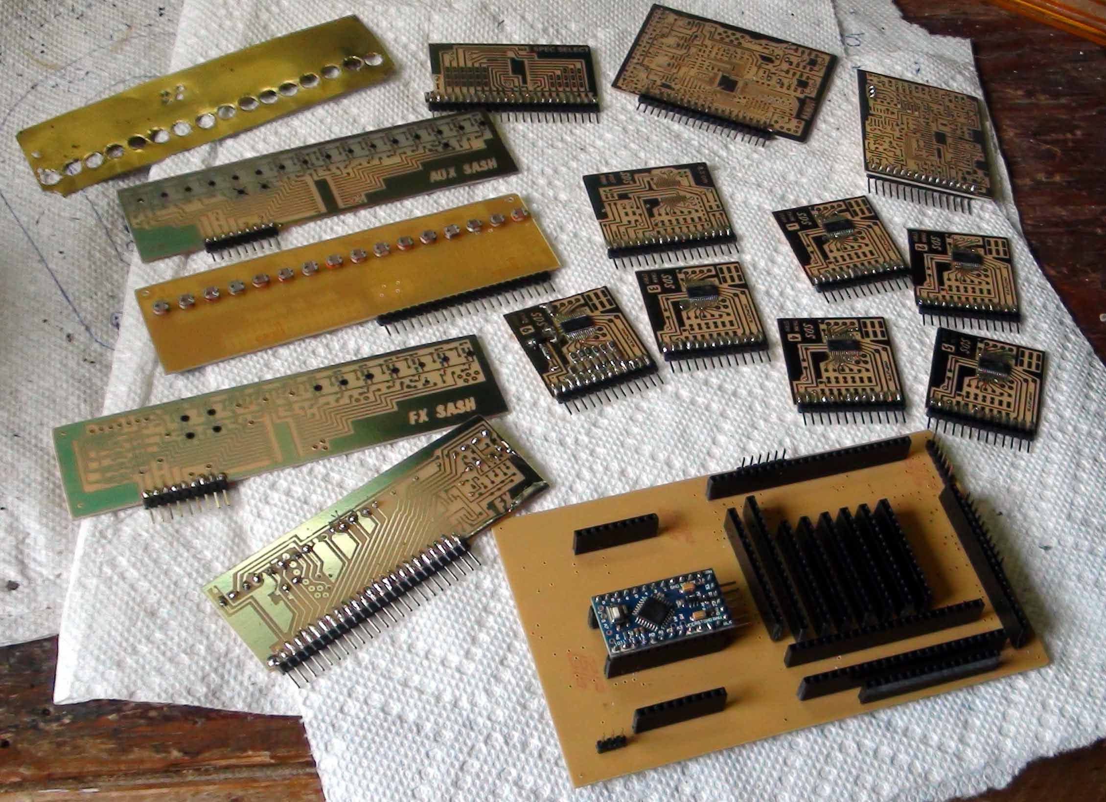
All of the
boards!
Imagine how big this would be as one board. Small parts aren't on yet,
ran out of time... |
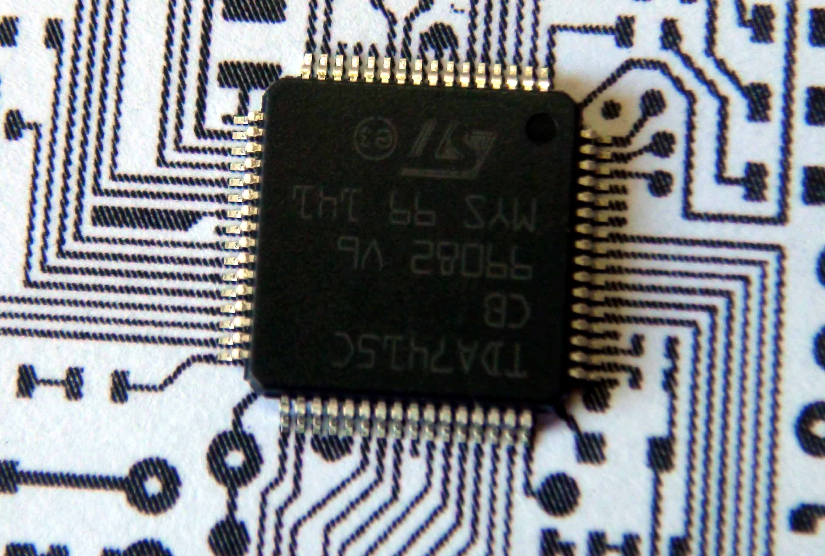
LQFP64 coarse
print test!
Just making sure all dimensions are correct. Pretty tiny 0.5mm! |
The board that
mates/mounts to a row of 1/4" jacks has the pre-amps on it. This board will
be shielded on trace side, just to be sure. Small headers connect the other
row of jacks individually.
Cheers, Sandy*
 to
The Effects (FX) Section
to
The Effects (FX) Section
.gif) ..to Show-in-a-box home page
..to Show-in-a-box home page |
|