|
VoiceLive 2 Hardware
Upgrades by Sandy Sims |
||
 |
||
|
VoiceLive 2 Hardware
Upgrades by Sandy Sims |
||
|
|
||
The VoiceLive Touch 2 is an
amazing piece of kit to add to your vocal arsenal,
but for my type of performance it is somewhat lacking in a few areas.
Lucky for me (and you?) I'm an electronics engineer so have started
to design some hardware accessories for this lovely machine!
|
As I've only just began using the VLT2
I'm still unfamiliar with some of it's functions but can already see things
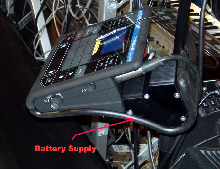
can be made better. 1) The first order
of business is a battery pack so I don't have to plug in all of the time.
Plugging in is really inconvenient and sometimes impossible 2) The second option is a custom pedal-6 for the
new firmware upgrade. I'll admit I haven't purchased TC's pedal 6, not for
the fact that I'm pretty cheap -Standard 6 switches for regular pedal 6
control SO, on to the battery pack first as I've just completed it! Battery Pack for the VLT2 I had originally thought of using a pair of
standard 4-battery holders and a double holder, taping them all together,
but that's so ugly and |
|
So off I went into Maya software and designed the case shown. While it's not perfect, it looks great! The bizarre shape is to allow room for the plugs. Here's the .stl's for it: VLT2batts.zip The 1mm indents for the Clips are slightly oversized to accommodate larger clips than I used here. The clips are from a bunch of solar lights I bought to tear off the little panels for something else, but they're only a buck each so... The opposing clips were soldered together and glued into place. I found that with my printer, the battery holes became smaller than anticipated as well as Duracell NiMH are way fatter than regular batteries, so the holes needed to be filed. Being paranoid, I series'ed a 10V zener +diode+100 Ohm resistor + yellow LED to drain off the high voltage post-charge state of the batteries down to 12.8V. It's kind of useless though as the VLT2 starts up at 13.6V no problem! I found a nice little barrel connector to plug into the VLT2. Don't ask me the size as I have no idea on those numbers or designations! *NOTE: **NOTE2: Test results: |
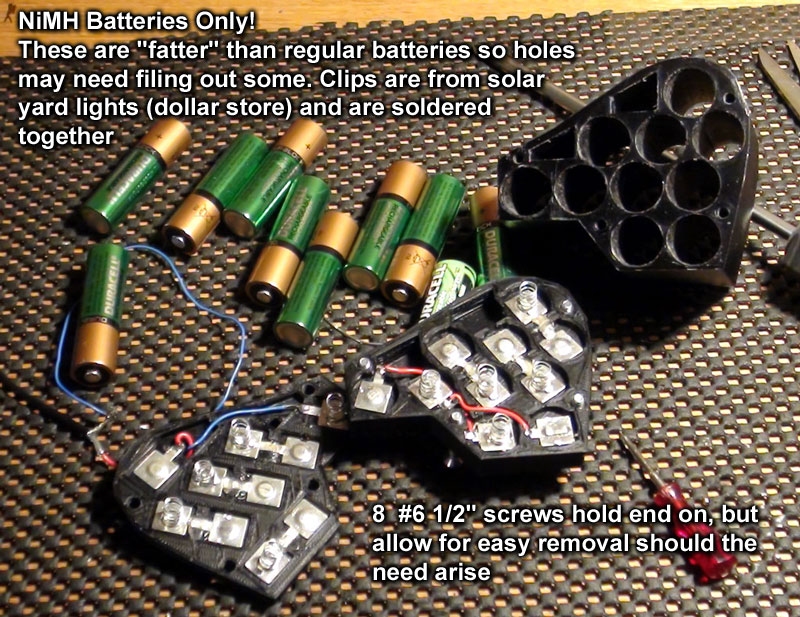 |
| - After metering the batteries, I
discovered the VLT2 only draws around 290 mA which was a pleasant surprise!
- I ran the VLT2 for 2 hours off of batteries, until the voltage fell below 11.7V. Then the next day for another hour with no issues.
Conclusion: The fit into the VLT2's bracket is tight, but the exposed cover (end) is slightly shorter to facilitate removal of the cover, and also to allow the rest of the case to act as a retainer. It won't fall out. I have thought about putting a tab off of one of the lower screws to further limit movement of the pack without gluing or affixing it.
PEDAL-6 for the VLT2 As mentioned above, I was about to buy a Pedal-6 when I realized it wouldn't meet my needs in the studio or on stage. I play acoustic instruments (guitar, sax, piano, pan-flute, accordion, etc) that requires both hands constantly, so reaching to tap a button is almost impossible. Believe me I've tried! With custom MIDI control, about 90% of the panel controls can be controlled via MIDI CC's. This is way better than just the pedals which I'd say is about 30%. Custom MIDI Hardware Benefits: Hardware: - The main processor in the circuit will be a
simple Arduino Pro-Mini (ATMEGA-328) for easy programming. Software:
|
|
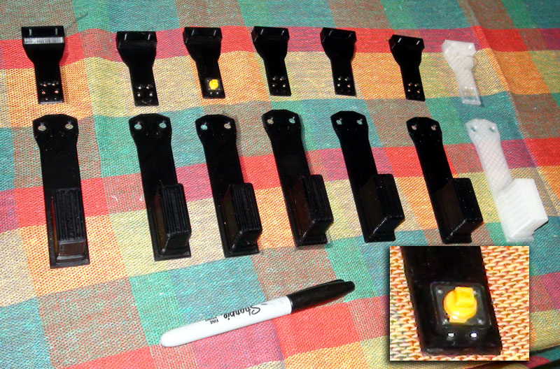
| The Box: 7 pedals were printed up with their switch carriers. #10 or #12 screws with nuts can be used to firmly bolt them together. The inset picture shows a 12X12 pushbutton switch in place. When pressure is applied to the footswitch head, the switch is actuated once it moves about 1/4". Under the head of the switch a heavy spring will be mounted. This is for the "feel" of resting a foot on the switch without accidentally activating it. The heads are about 1 1/4" high to be able to go through 3/4" plywood (or cedar) and the surface panel (below) The switches must be soldered on the other side but they fit fairly tightly in place so shouldn't need gluing. The White pedal is semi-translucent so could be illuminated if required. This is all "by gosh & by golly" really! Here's the .stl's (and .obj's) for the pedals and switch mounts:
|
 |
|
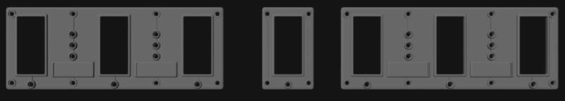
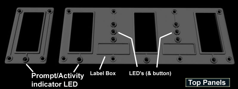
Now the switches & heads are done, a panel design
must be made to avoid the rough edges of wood. These panels are held in place with #4 wood screws, quite a few of them. Better safe than sorry! I have completed these panels but as they are black they show poorly in a photo for reference. I put some raised lips around the LED holes to protect them from footin'- puttin' as the panel is only 1.6mm thick (to save plastic, money, and the environment!) Under each pedal is an LED that may indicate
active pedals or pedal states. I may use RGB LED's here. As these holes are
3mm and the RGB LED is giant at 5mm, they my need to be dremelled down to
fit the holes. It was an after thought... Between each pedal is a set of LED's or LED's
and a button switch. (not sure yet) The little frames are for marking pedal functions. These will be painted silver so black felt pen can be used and erased with alcohol if required. |
|
The lower picture here shows the general arrangement of the panels. The center is of course for the white 7th pedal. This pedal will control MIDI<-->Pedal-6 modes and likely MIDI presets 1 to 3 or 4. Pedal-6 mode will turn off all of the LED's to minimize draw. The power switch (which will be on the back me thinks) can then be turned off as the latching relay will be in normal pedal-6 position. The .stl's & .obj's for the panels are at VLTpedcovers.zip . I must mention that these footswitches are 60mm apart only, which suits me as I don't have "man feet" but if you are going to use these .stl's, the actual sizes can be larger up to 30%? the pins on the 12X12 button switches may need a bit of bending but hey, you won't have to drill out the 3mm LED holes larger!
|
|
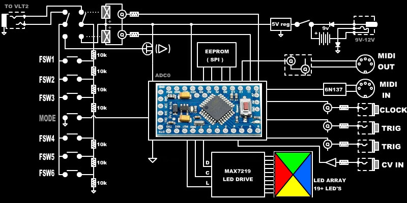 |
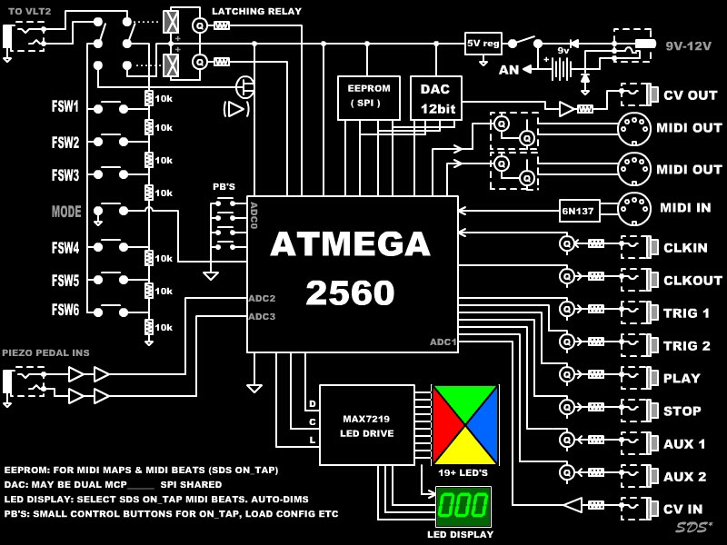
This diagram is the basic idea of it. It's not super complex! The pedal-6 uses a resistor ladder and when switched over, so can the Pro-Mini in the same way. There will of course need to be some timing and de-bounce routines internally, and perhaps an RF trap before the ADC input. The modular inputs (clock, trigs, CV) can be used to trigger events from eurorack modular signals. The primary for usefulness is the clock. The CV input could be used to control VoiceLive's harmony key along with a VCO let's say.. So that's about it for now, gotta go! I'll post proper schematics & more specs etc. once they are done. |
|
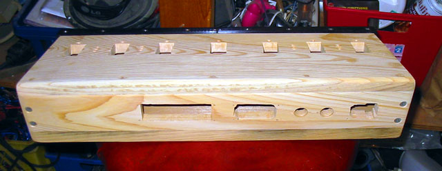
Update: Jan 23rd 2018
Had some down time over the week so
fabricated a case and worked out the jack arrangement. As the diagram
above shows there are jacks to interface with eurorack modular so I
decided to keep them all together and recess them with a 3-D printed
panel. I have added a clock output (to work with MIDI) and another CV
input. There's a couple of extra jacks for whatever other ideas that
will pop up in my head between now and completion of the MIDI side of the
project. |
|
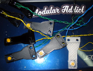
| The wood case was a bit of a
challenge for me as it's been a while since my last "nice" wood project,
but wood seems to be the way to go. I could have welded a metal case but
this looks nicer! :)
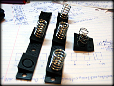
The springs for the pedals must be mounted at an angle to follow the case, so I 3D printed mounts for the 6 pedals, and a little one for the center (MIDI) pedal. |
 |
| The "off grid" power
will come from a 9V battery that will be bypassed by a barrel connector
the same size as the VLT2, but bi-polar meaning either type of adapter
(wall wart) can be used. There will be a little full-wave bridge to do
this. The eurorack op-amps will need a bit more than 5V so may use a 6.2V
regulator for those.
|
|
|
|
|
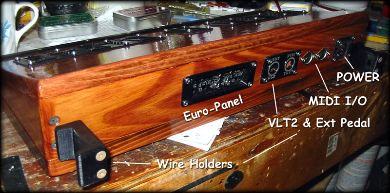
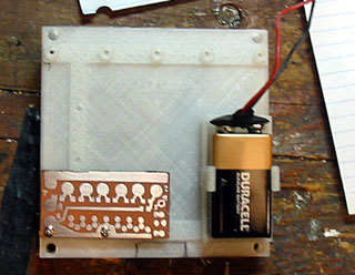
| This photo shows the back panel, albeit not
fully jacked yet. I made a pair of large wire holders to, er, wrap wires
around. It's good for quick setup on a crowded stage and keeps them in
order! The first 1/4" jack patches over to the Voice Live 2 and the other is for an external pedal (possibly a piezo pedal) as I'm thinking on perhaps integrating a SDS On-Tap (SDS Tap II) which is a special drum pedal I designed 3 years ago but never produced (Beat buddy came out and even though it's very different, would have been major competition) The other jacks are MIDI I/O. This MIDI out will of course patch to the VLT2 but the MIDI in can come from a DAW or controller. As the VLT2 is the end of the line MIDI-wise, I may add another jack splitting off, not sure yet. The pedals will send their control data but I also want DAW control over some functions so in a way it's an internal MIDI-merge. >>To the right is the PC board mount that stands on little legs to clear the center pedal. I'll show more of this shortly. The little PC board shown is temporary with just the standard Pedal6 circuit. Below that photo is the 12x12 tactile switches wired and ready to install. The aren't in yet, perhaps tomorrow. I've decided to mount all of the switches to a length of aluminum angle as I don't want to pop 14 holes through the nice case!
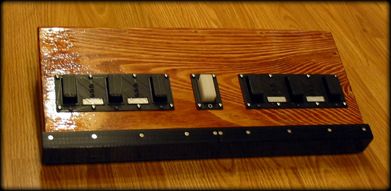
Below is the case pretty much finished. 3D printed a guard for the front edge (as it *is* wood) from PLA that wraps around as a protection. . The little "windows" are for marker pen and arrows in case I forget the last configuration! Alcohol will remove it. I'll post my experiences with the basic pedal 6 arrangement first. Until next time, cheers! |
|
| March 11 2018 It's been a while as I have nearly no time to do my own projects but I finally got around to wiring up the Pedal 7 with the really basic board which is the components to the far left (10K resistors etc). It works great! As can be seen, the the proposed schematic has grown a lot. This is to mainly integrate an SDS On_Tap into it, and the extra MIDI port so the chip had to be changed to an Atmega which has 4 USART's, lots of I/O and could be just the Atmega arduino board. In my design it will be integrated but if you decide to build this project then an arduino board can be used. Anyway, the SDS On_Tap: The key feature of the On_Tap is that the beat
can be inserted after the song is underway, i.e. |
 |
| It sounds super
simple, and it is really, but I've used this is performances for at least
3 years and it's totally cool to use! One day I may release the On_Tap as
a guitar pedal, but for now I'll treat this as another step in the
evolution of it. So back to the
Pedal project... VoiceLive Touch2 "Notes Mode": In the MIDI programming I'm going to have to insert a "sustain" message, or just lock note-on's (up to 4) with timing so the harmonies are changed as I change chords in the piano. This seems simple enough, but might not be. The way I play, mostly, is the chords are changed by releasing all keys but sometimes I hold a key or two and change. This will need to be detected to release old notes and replace them with new ones. Always in 4's as this is what the VLT2 likes. Another issue: Keyboard limit(s) The EEPROM: Quickly things are getting complex, but it seems really logical to integrate the SDS_On_Tap as I've been meaning to retire the old one that has a more limited memory.
|
|
Dec 1st 2018 Update: After a long period of doing other things, I have decided to continue the "Pedal 7" project! I have been using it as a pedal 6 for the last few months but am ready for more features (as with the previous design) but have added even more since: 1) SDS_Tap built in as before but does Drumloops + Entire MIDI Songs. Also sends control & sync to VLT2 as before. 2) A built in sample player. This will not only augment the MIDI drums with real sounds but can do entire loops. Sample memory is SD Card based but holds over 20 minutes of audio without SD Card. This is to avoid SD Card latency issues too. 3) Audio EQ. External audio can be fed in and
run through the sampler EQ for level and FX that can be MIDI-song
controlled. The Main audio out will go to VLT2's audio in. |
|
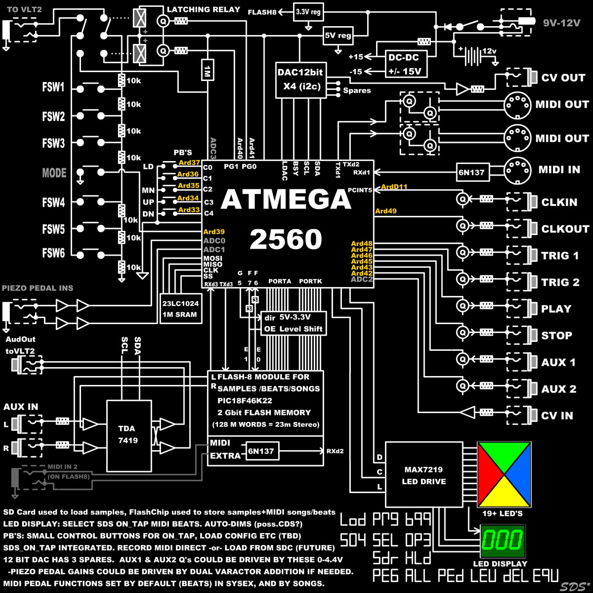
| As can be
seen in the new basic schematic, the sampler section is old school
parallel bus. I prefer to avoid the huge overhead of DSP, Codec's, and Arm
Cortex power consumption that would be required to do it any other way. The flash PCB is actually a PIC controlling a 128Mword flash from one of my products, the Reflex LiveLoop Expansion board. The Atmega basically gets the MIDI song/drumloop data from the flash also, and then loads that into the 1Mbit SRAM via i2c. Samples are handled / mixed by PIC18F46K22 on the Flash board, (I'll post a schematic of that eventually) then send onto the bus of this board to the stereo 16 bit DAC (hidden inside box also). The ADC5547BRUZ DAC is rather expensive ($28) but I had a few extra kicking around so used one of them. The bidirectional level shifter (2x8) is a 74LVC4245A that also protects the Flash PCB's bus. For the Atmega chip I ended up using a little breakout board that greatly assisted in the design on a single sided PCB. The PCB was photo-etched (made larger via's in KiCad) then CNC'ed the holes. This was the first time I've ever crossed the two methods and it worked great! The only difficult part was getting the PCB image size correct so the CNC wouldn't end up drilling holes outside of vias and other horrible things. I will also post the KiCad schematic etc. as this is only a basic description and I have little time at the moment! Cheers, Sandy |
 |
| March 5th
2019 Update: Well it's been a while!
I have the Pedal-7 finished (as of Feb 25th) but find it hard to
stop as I have been using all of my spare time on this project. This is totally going to sound like a
bragging session but, if you have a VLT2 or are designing a hardware MIDI
sequencer this will be of interest. VLT2 The latter presented a real issue for my singing & looping style. I tend to begin singing, or sing the downbeat slightly ahead of the actual downbeat ( this is normal in swing styled rhythms ) so it would chop of the very first bit of my vocals or cycle at a point that I couldn't well duplicate to close the loop. I know common looping practice is to "run into" the start of a loop, then run into it again for a moment to close any gap at the end, but this seemed and felt very limiting! It also caused a slight problem with a MIDI sequence controlling the Looper. One would have to be careful to leave some time before ( >1 beat ) starting the loop and measure that time for ending it. Because of this, Loop re-triggering FX are out, and so are pauses in the loop as they will start at the wrong part of the loop. Ugg! So the solution, as ugly as it seemed at first, was to use the MIDI sequence (Song or DrumLoop) running in the Pedal-7 to quantize to the following 1/24th of a quarter note (which is standard MIDI clock timing) and quantize to bars! That's an "arm to end" on every 96 clocks. So no matter where the loop starts, it will always align to the next bar in the same offset position. So... how will the VLT2 stay in sync with the
Pedal-7 if the metronome, aka clock sync ability, is disabled? Well,
simple...or so I thought. Use the VLT2's Looper Play re-trigger command to
keep the alignment. This did not work as well as I'd hoped. I guess
it's to do with an oversight on the VLT2's internal timing while under
MIDI control. Dealing with Play re-trigger in normal case use is via a
finger-touch on the Keypad, which can be out up to 50mS either way because
of human error, finger velocity etc. OK, so it doesn't work then?! No, it does work if there's no sync. I discovered that my internal MIDI sequencer timing is so accurate, it will track within 1/4 second over 10 minutes! This is without fail. So I implemented a "sync request" on the Alternate Pedal switch (center pedal switches to 2nd set of pedals) that will do a re-trigger Play on the next loop point if desired. The Play re-trigger works perfectly now as well, doing breakdowns with your foot is fun ( and challenging ha ha! ) when being creative. Sample Polyphony: MIDI Loop Recorder: I can see this useful if I want to switch to guitar or some other instrument but keep the progression going. I don't know how much I would use this live, but this Pedal can be controlled via MIDI so could be armed & ended by a playing song, which is a more likely scenario. Live Self-Clocked Recording
(with metronome if Desired: I have recorded a single session over 45 minutes this way, and it'll hold 100 Songs and 100 DrumLoops! True Live Notes MIDI Harmony: For my own use on the other hand, I know my
playing style so could fashion an algorithm to suit. In a simple view,
this amounts to the following: I have also created my own harmony keys range (that can be changed by each song/DrumLoop Loaded if required) rather than just High or Low keys offered in the VLT2. As a woman, most times I don't want baritones harmonizing with me, or pixie babies, just other girls my age! As I am all over the keyboard neither is good for me, so a "window" of opportunity was to create a window of notes!
|
|
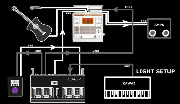
| Besides the VLT2 and my new
Pedal-7 Sequencer, there is another piece of gear I should mention. This
will make the portable experience far better than lugging my Yammy V-Drums
everywhere! The MIDIPLUS Mini-Engine Pro: In the "Light Setip" diagram at the bottom left corner is a little GM MIDI box that is about $80 US, made in China, and sounds great! The reason it sounds great is because it's using the Dream (TM) France SAM5504 chip (along with an STM32F40(5?) microcontroller, even though the Dream chip doesn't need it.) Each Channel (including percussion) has a Cut/Rez Filter, standard vibrato mod wheel etc, and A/D/R envelope controls! Quite a lot for $80 eh? ($4530 CAD) It is 32 bit so sounds very nice indeed. Stuff sounds real and can be modified into our favorite electronic music instruments by monkeying with the above controls. The down side is typical Chinese buggery. Even
the the Dream chip can handle multiple instrument access, several drum kit
variations, and other features, whatever firmware they have put into the
STM chip kills it. Perhaps for future model feature releases (ugg!) or
just because they had no idea what they were doing.
|
 |
| I could go on and on and on about the Pedal-7, for pages and pages ( well 34 pages - here's the user manual for ideas!! ) but I won't. Suffice to say, this is the "funnest" thing I have ever made. It can hold 100 Songs, 100 DrumLoops, all tap tempo playable and variable, can be re-clocked on the fly via external Eurorack Modular clock ( great for fast-forwarding! ) or DAW Sequencer ( resets to start instantly) , it can provide a clock for other MIDI instruments or Eurorack Modular, can hold up to 100 directories with 100 samples in each, has 12 accessible Pedals assigned with any of 31 functions, sends Trigger/Gate pulses from any Clock Division or notes in a MIDI Sequence, saves and updates Song/DrumLoop parameters & Options via SysEx files on an SD Card, has a SD Card SYNC function to add samples or update default/Dong/DrumLoop parameters automatically, can output Control Voltage (via CC or Quantized from MIDI Notes), can read trigger/gate inputs to control Pedal functions or play MIDI Notes or a Sample, has 2 separate MIDI Output Ports and 2 MIDI inputs (merge), has built in EQ and Auxiliary Audio (stereo) I/O Mix, Controls the VLT2 via MIDI CC's, Special Notes, and voltage inputs.... OK enough! I will be making some videos in any case and I will post then here Cheers, and thanks for putting up with me! S*
|
|
|
Disclaimer: This is not an
instructional page to build or manufacture the above project, nor are there
any guarantees of accuracy herein. This page is an "of interest" discussion, and the project is intended for my own personal use. If you have any questions, or wish to pursue this project, you may contact me (Sandra) at fresh(at)freshnelly.com Project Copyright : Fresh Nelly Musik |
|
|
![]()