| Day 407 |
 |
WindGen. Solar panels |
| Day 407 |
|
WindGen. Solar panels |
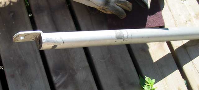
| The MarineX wind generator has sat in it's box for the better part of a year now, like a caterpillar in it's cocoon. Today is the day it will "fly"! A strong pole ( the manufacturer was very specific as to the schedule of the pipe! ) is required and must be solidly mounted to the boat. Stainless is a given, and mounting to the radar arch is obvious. The height must be such that nobody looses an eye, scalp, or ear. The blades are very sharp as noted all over the packaging, in the instruction book, on the blades, and by Gena's son who has been using the "land" version of this generator. | ||
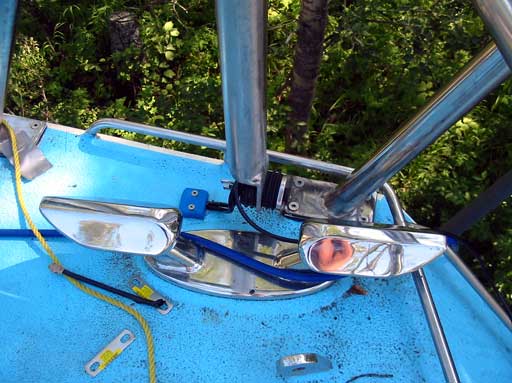
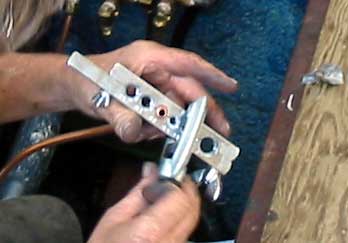
| Sound dampening is a
strong concern as many a sailor has complained about the noise
these machines make, particularly on steel boats. As can be seen
in the photo ( right ) the rubber from 2 compression plugs was
used to isolate the bottom part of the pole. A small grommet
must be used to isolate the bolt between the two.
|
 |
||
|
|||
|
Now the only problem is, there
has been no wind! A few breezes came by but no movement. In the manual,
they mention the generator needs a burn-in time of a couple of hundred
hours and until then the generator may seem sluggish. Sluggish must mean
"doesn't move at all".
Later that night a T-storm came through and he went very fast! It seems there needs to be sustained winds though. Here there's trees everywhere and the wind blows everywhere, never in a straight line. I guess the real test will be once the boat is in the water. I had hoped we could get some free amps for the batteries but seems it won't be so... yet. This brought me to the mounting of the solar panels. This will be a guaranteed charger of the batteries. |
 |
|
| We have decided to start out with 4 panels. These are the flexible type, designed for hanging from stanchions, temporary use on decks, roofs etc. hence the grommets. | |
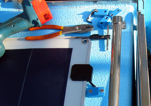 |
They are about as thick as cardboard and yes are very flexible. We have pandered how to mount these for ages. Drilling 24 holes through the roof ( one screw for each grommet ) or 48 using proper mounting clips is horrifying to us! Glue ( goop for holding power ) and silicone are the next choice. Silicone ( silly cone as I call it! ) sticks like, er..., glue to the hippo coat on the deck. It is basically unremovable so hopefully this works. |
 128 watts of power!..Well, potentially.. |
The same method of feeding the
wire through was utilized, just smaller pieces of Lexan. This took the rest
of my day as I broke a tap while tapping 10-24's for the wire clamps.
Searching for a new one took time. Too much time. The weather was hot, 35ºC, and so was I. Arg! |
| As soon
as I connected up the panels ( all in parallel is the standard for 12 volts
) I noticed the battery monitor showing a couple of amps. It got up to near
4 amps even though these panels together can do 8 in full sunlight. That's
the key word, "full". Upon inspecting the panels I realized the sun is
partially obstructed by trees! The only time trees aren't blocking half of
the panels is first thing in the morning when the sun is at too much of an
angle to make a difference. With all of the "stuff" these poplars and
accompanying birds drop continually onto the boat, now blocking the sun, I
am considering chopping them down. These panels have diodes across the cells. This means that if some of the cells are blocked, the diodes carry the current across from the ones that are. Good idea in a situation where sails will be blocking sunlight. One more thing, if you haven't heard enough about solar panels already, in low light conditions i.e. T-storm, sunset, the voltage still measured around 20 volts, but the amps were down to .1 ( 100 mA ) or 1.2 watt. Not bad! |
|
|
|
|
| Gena worked
inside the hot boat ( remember it was 35º outside? ) which had become almost
unbearable until I opened the hatches over the pilothouse. She put in the
big black water tank to start. ( Photo above ) and hooked up as many joints
as possible. It's time for yet another trip into town for more fittings!
There must be a bypass on the cooling system as previously mentioned. This
will enable "fine tuning" of how cool the engine runs by not allowing all of
the water flow to go through the hull cooling system. Something like how a
thermostat works in a car. There is also a thermostat here, but because of
the size of the cooling panels, the thermostat will likely oscillate wearing
it down and creating an uncontrollable scenario with engine temperature.
Gena figures the system will take 16 gallons ( 8 anti-freeze & 8 bottled water ) to fill. She still needs to get some fittings for the bleed-offs at the ends of the hull cooling boxes. Guess valves are needed there. |
|
| Next in line was the fuel system
lines and valves. As we have 3 tanks, 3 way valves are needed for the fuel
intake / return lines. This looks complicated to me, but Gena assures me it
isn't.
Labels! I want labels! One valve controls which tank the fuel is coming from, and the other controls where the return is going to. This will allow us to move fuel from one tank to the other, good for emptying the upper tanks to fill the lower tank. We must be careful though as the overflow/breather line will only hold so much before fuel starts shooting out the end! |
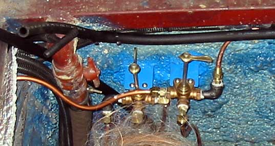 |
| As everything is copper lines ( pretty now but will probably end up green if we don't paint them) flaring is required to mate connections. Gena has had lots of experience with this tool during the building of her house and connecting up out diesel furnaces at home and at work. Guess she has a "flare" for it (lol!) whereas I haven't a clue how to use it. Guess I should have been paying more attention. |
 |
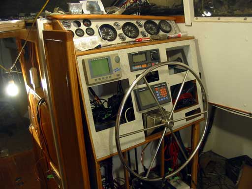
| Just an update on the
continuing dash project: The arrangement of the gauges has become quite different from the 3d draft I did as more needed to be added. The temperature gauges mounted are for the engine oil, water out, water in and transmission. Handles have been added to make it easier to remove the panel, plus it looks cool! The GPS, autopilot, & compass displays have been re-arranged to allow for easier viewing. For the GPS, directly above the steering box, I made some lexan shims to angle it up a bit. Another expensive LCD product without polarization adjustment!! I don't understand why polarization adjustment isn't a standard feature in everything. At work we have the same problem when installing AM/FM radios in big trucks. Most of them are up in the head liner and the displays are made for dash mounting, i.e. looking down on. When up there, the display magically disappears. The compass LCD has driver chips I am familiar with so I pulled it apart and put in a potentiometer so it can be adjusted. I think the Furuno would require a negative voltage so that's out. |
|
  |
Day 407:
14 hours - Mounted Solar panels, wind generator, wired everything in, mounted
coolant header tank, connected up fuel system ( except filters ) to engine
from/to 3 tanks.
To DAY 406 |
Follow Iwalani's voyage around the
world
...this is
not a watered down, sugar coated tale, but a "no holds barred" |
To DAY 408+ |