 |
||
| An "ocean music" research project by S.Sims |
 |
||
| An "ocean music" research project by S.Sims |
-www.thebigsailboatproject.com-
| Theory: | |
|
|
|
| What if a person could hear
the sounds of ocean waves as an audio recording? Not the sounds you'd hear
while walking on the beach, or even under water, but the actual shape of the
waves as audio.
As everyone knows, audio is just
a series of waves that travel though the air to our ears. Those waves can
produce any sound we hear from a high whistle, to a booming sub, all
depending on how many of them happen in a given time. |
|
| Wave cycles, or
periods, in the ocean are 3 seconds to 15 seconds depending on
location, weather, sea conditions etc. These frequencies are far too
low for the human ear to hear, which is probably a good thing as the sounds
from the ocean would probably drive us crazy! But if these waves are sped up
by, say, 1000 times, we'd be able to hear them! A 4 second long wave would now be (.24hz * 1000) 240 cycles per second, about B4 on a piano. A longer ocean swell if 12 seconds, would be 83 cps, or a B3 on the piano. |
|
| This would all be pretty boring
if ocean waves were just even sinusoidal shapes, but they're not. In fact,
waves exhibit the same properties as audio waves when different waves are
mixed, distorted by land features, even the Doppler effect applies. These "mixes" of frequency create other frequencies known as harmonics. These would come up as other notes, perhaps with less level, but still enough to create a symphony of sound. Then to add a sprinkle of spice, randomness, such as a gust of wind forming ripples, a boat's wake, or rain, will make white noise. This might resemble a whisper, or a cymbal, or just a hiss. |
 |
| Recordings, in order
to produce any length of audio, would need to be taken for hours or days at
a time. No two recordings would ever be the same, but I believe changing
conditions, like a storm approaching, or the wind veering, might become
recognizable over time...if recorded from the same location. Different locations will produce totally different sounds. Obviously an inland waterway with it's 3-4 second waves will sound different than the middle of the ocean with 8' swells spaced 12 seconds apart and 2 second "chop" on top. Because 24 hours of recording will produce just over a minute of hi-fi sound, any slight changes in wave shape will make big changes to the listener! |
|
|
|
|
| Sensor System | |||
|
A method to
be able to sense the height of the waves is the next logical step. This part
will get a little technical, so if that's not your thing just skip past all
this to the results. I have a bit of experience with level sensing as I had to design an electronic level display for a stainless waste tank in our boat a couple of years ago. I went through several ideas, and produced a couple that didn't work well because of magnetic fields or particles in the black water. |
|||
| A simple way to get the level of
waves would be to just mount a float on a stick connected to a variable
resistor, or potentiometer. (right) This would get the basic shapes of the
waves, but the floats weight and size would smooth off most of the small
variations. The resulting audio would be clean tones, but not much else.(
see diagrams to the extreme right) This might be desirable, but I'd rather control frequency cut-off in software via the sensor speed or in audio software. |

|
||
| A magnet sliding up
and down a pole would yield similar results, but in a more stepped fashion.
A stainless rod might work. As the rod gets deeper, the resistance decreases, thus giving a nice representaion of wave shape. The problem with that is corrosion and build up of oils etc. varying the results, plus we have a steel boat so the sacrificial anodes there would probably cause problems. |
|||
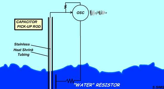
| The final idea I came up
with for the septic tank should work well here. Insulating a steel rod from
the water will create a capacitor-resistor when under water. The deeper it
is, the higher the capacitor value will be! After searching around on the 'net, I found that something like this already exists. They are called "wave-staffs" and are used by NOAA and Env. Canada (and probably world-wide!) to measure wave height off of buoys and fixed stations. I'm not sure, but likely they are very expensive, and they don't output exactly the type of data needed here...plus stand-alone logging of data is very important, especially in a remote location. Which brings up the next problem. To get decent resolution of the wave shapes, I want to sample at least 10 per second at 12 - 16 bits... |
 |
||
Memories.....cool..not cool...cool again
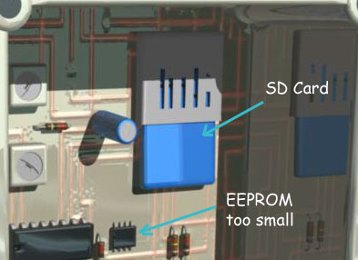
| For stand-alone data-logging, this is a LOT
of memory. In one 24 hour period, there will be 1728 Kbytes (1.7meg) of
data. This is too big for any EEPROM's out there. Using a DRAM would work,
but it's a lot of trouble to interface and if the batteries die so does the
data. A few days ago, I entertained the idea of using a MMC or SD
card because they can hold massive amounts of data, and eliminate any data
transfer problems, (i.e. RS232 download at top speed is over 6 minutes/24
hour period!) as it can be removed and plugged directly into a PC. Now
that'd be cool! Looking at the file system on these cards (FAT16 or 32) I was almost scared off. Way too complicated. But after studying the SDC "disk level" interfacing protocols, and deciding to switch to SPI communication mode instead of the default SD mode with it's CRC7's, it's beginning to look a bit more familiar, like a complicated EEPROM really. At this time I will ignore the horrible FAT system all together, just to get the hang of talking with the card itself. Plus, if I don't develop an alternate -non-MS- file system, I won't be able to give it out/post it/sell it to anyone/ anyway because Billy Gates will hunt me down and run over my little yacht with his big yacht! |
 |
| I'll spare you any more techno garb on the SDC as it can be found all over the 'net, (SDC standard) and I really don't know what I'm talking about at this juncture anyway. | |
| Circuit |
| I have changed
the circuit 3 times on paper, and about 20 times in my head, pivoting on: Cost/time/size/probability that'll it'll work/anger factor from Gena because I'm wasting too much time on it... and this scan is the latest written on the back of my paycheck envelope, guess I'd better cash that actually.. Please disregard the mess at the bottom. |
|||
| At this point, the sensor is feeding a 555
timer setup as an oscillator. The 4510 (4516) divides the signal by 10 (8)
to allow a longer time for the PIC16F74 to count the full pulse width. If
the capacitance can be around .001uF at the 5' mark of the 10' rod, & R=1
Megohm then the pulse width is only 1ms, which means the PIC (16mhz clk/4/8inst.loop=2uS/loop) can only count to 500. With the /10 it can count to 5000, better resolution. This could be doubled again (or more) in SW but 1/8" is probably enough. I'll reserve that thought for R&D.
The thing connected to the transistor on the left
is one of those electronic clock ticker modules you find in most
mechanical clocks. I used this on a WX logging system last year and it works
well, Use a resistor ladder to get 1.5VDC then amp back to 5V with a 3904 Q.
It only cycles a pulse every 2 seconds, so a "tick" must happen on each
toggle. |
|
||
| The S-RAM is a serial RAM
and must be used to store data until it can be written to the somewhat large
512-byte buffer of the SD Card. Also settings data can be stored if a quick
update is needed. It will be a manually configured SPI bus. The real SPI bus
will be connected to the SDC. The RS232 was going to be done without the
MAX232, but for simplicity it will be used. I want it to be shut down during
RECORD mode so it doesn't waste power.(The 2 Q's) The only time it
will be used is when the unit is connected to the PC to either change
settings (sample rate, clk rates, output format etc) or to dump the card
before FAT is installed. The Power Supply 6 NiMh batteries (AA-2000mAh)
will be used, then regulated down to 5V and 3.6V and 1.5V. The SD Card takes
a whopping 50-80mA during a write, but has a sleep mode after 5ms, so all
considered, on a 6.4 second update rate (512 bytes[blocksize] / 2[bytes]
/10[per second]) only 13,500 writes (6ms each) will be done in 24 hours = |
|||
|
Circuit Description Once communication was established, the
next target was the serial S-RAM. I've been outta it for a while so I didn't
even know these existed!(64k-bit:23K640) After that, I wrote the routine to sample the
sensor oscillator pulse width, and send it into the SRAM. Cool! It works. |
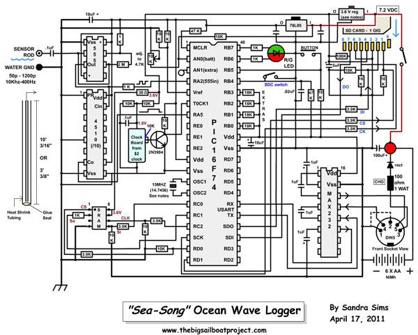 The "as built" schematics. This design works fine CLICK IMAGE TO ENLARGE |
||
| Sometime the next day, I began
writing / reading /comparing data. I successfully loaded 8 megs of data down
the RS-232 (a 20' long telephone wire) without a single error! Amazing! With
some refinements to the interface commands, it's all ready for the big test
on the ocean. I'll cover the commands below.
Anyway, on with the circuit description. To remove any confusion about the RS-232 9-pin
SubD female plug connections, the 5 pin DIN --> SubD is as follows:
pin 4 --> pin 3 pin 5 --> pin 2 pin1(gnd)-->pin 5
|
|||
| Last, but not least, the SDCard socket. Most
have a switch that connects when a card is in, and a switch to sense if the
"read only" switch is in write position. I ordered a socket from Digikey,
but it ended up being the micro socket, so I had to butcher an old reader
(no good anymore because won't do SDHC) to get mine. Try to keep the
traces to this connector shorter than 2" as data flows pretty fast.
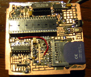
Well there's my hand-drawn layout of the board. Just a mention: IMHO the best etch resist pen is the Staedler F (or SF if you can find it!) and it works well with the new etchant Sodium Persulfate (Not to be confused with Ammonium Persulfate which eats pen ink off faster than the copper!) The whole project is going inside of a Hammond waterproof enclosure (also from Digikey) and I bought an extra deep one this time because size doesn't matter,(bigger=better if it ever breaks free at least it'll float instead of sink!)
|

 |
||
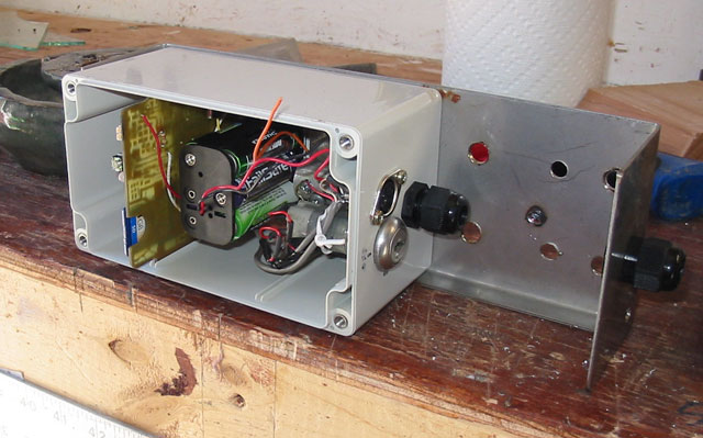
| The box is now mounted on a stainless bracket
made from a perfectly bent piece of stainless plate I found at the scrap
yard. This is to (a) securly mount the thing with U-bolts, and (b) to
re-enforce the support for the rod(s). Notice I used a key lock power switch? This is because a toggle might be too easy for a curious kid to come along and flick off, or a seagull for that matter! The black thing is a cable gland fitting, but I'm not using the gland as this side faces downward. The lid, below, has a cool pushbutton seal. I painted out a swath of silicone on some saran-wrap, let it dry, then clamped it under this plate I found! It's a perfect seal, but lets the LED shine through and pushes in to click the button.
|
 |
||
| Test #1 |
|
A two hour test proved enlightening, and also a bit of a disappointment. The candle wax I applied to the rod to give it some hydrophobic properties promptly fell off and ruined the recording after 2 hours. Several curious onlookers demanded an explanation of what we were doing, then once satisfied, allowed us to return to read the results! |
||||
 |
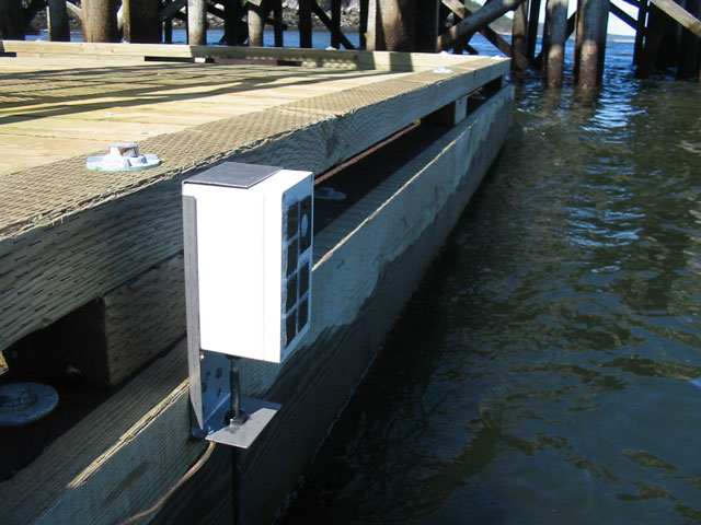
Mounting to the dock was no
problem at all, but the position wasn't ideal. The waves were rolling nicely
in, but they were hitting the pilings (see photo) and bouncing back along
the dock. I can't mount the sensor on a piling as the tide will come up and
drown the box, so this will have to do for now. As the wax fell away, and the rod became more and more saturated, the level predictably came up and in the end, all that was left was noise.
I think the "noise" is created by sheets
of water randomly slipping off the rod. And that spike near the beginning,
(blown up below), may have been water splashing on to the bare section of
rod. Guess I'd better coat that!
|
 |
||
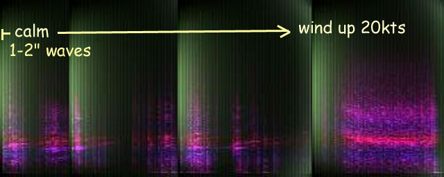
| The little spectrum shots
show the peak frequency, and an envelope a bit higher. Also there's some
lows in there. The 3rd spectrum shows noise near the end. If you want to hear the first recording, raw as it came off the sensor (warning: not DC centered!) click govydock-raw1.wav (right-click to download) govvydocks1.mp3
is a filtered version at full/half/quarter/eighth speeds. |
||||
| Spectrum 1 Spectrum2 Spectrum3 | ||||
| Today's test will likely produce better results, but I think the weather has calmed some so there might not be as big waves as yesterday. Cheers!;) (April 19) | ||||
| Test #3 |
|
As test
#2 was a total failure, bee's wax, which yielded little more than some
crackly sounds and an almost imperceptible whistle, I'll skip it all
together. Test #3 was almost a failure, but demonstrated the possibilities to come! After discovering the obvious (to some) I decided Teflon(r) is the way to go. It's not a "super-hydrophobic" material, but the next best thing. Then it dawned on me that my partner Gena has some teflon plummers tape in her goody bag! So off I went wrapping the staff tightly with it until my hands hurt, and we gingerly drove down to the warf and attached sea-song as before. |
|
| Yes, another
disappointment. (photo right) The same crackling and popping as before, and
a slow curve that indicates saturation with water. The total record time was
5.5 hours, and the sea went from calm all day, to a real blow within the
last hour. This waveform taken early in the recording looks the way one would expect in calm conditions, and there is certainly audio qualities to match. The waves were 1-2 inches. But once the larger waves started in, you can see the area that leaked filling in the smooth curves that should be there with a constant line... giving it a stepped look.  |
* *Click image to hear it! * * |
| After some processing, mainly to even out the levels (which is why there's such a hiss) and limit the popping, a surprising result emerged! Over each hour, the frequency definitely increases. This happens about 5 times, and they overlap with 2, sometimes 3, distinct tones! Then as the last one is fading off, a sharply enveloped swish downward, like a jet that has flown over, announces the incoming winds and larger waves! | |
| For a failed test, things
are looking up. I've already discovered a really interesting feature of
waves. They can oscillate upward, one group after another. This spectrum analysis, pieced together from live readings from the recording on a very small screen!) , clearly shows the ever rising frequencies and even the dual tones present, despite the horrid audio quality and missing sections. The last frame is of course the sudden drop from a very high tone to start. The full height of this spectra-graph is 5 kHz to give a perspective. I'm still not sure what this upward curving is, or how it happens, but it's really interesting isn't it? Especially since Test #1 seemed to be even-toned. |
 |
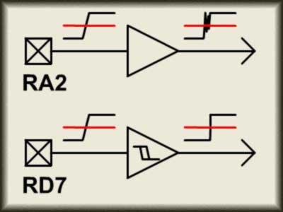
| Even though I know
what is causing the waveforms to distort, and have ordered some PTFE heat
shrink tubing (very expensive stuff!) to remedy it, Those occasional pops
are still present. During supper I realized that Port A,2 ..... where
the 555 is inputting to, may not be a Schmidt trigger input,
as some inputs aren't on the 16F74. Sure enough! So the new input from the 555 is Port D,7. (illus. right) but I'll leave the /10 input at Port A,5 as it's quite fast. Now there will be a dry spell on
this page, while the snail-mail slowly brings my PTFE tubings closer and
closer lol! I've decided to add and automatic centering routine that
executes on record start, and samples (12 or 24 secs) for and average, then
centers the .wav file at that by subtracting from the samples to try to
center at zero. |
 |
|
...as test #4 was a complete failure, I'll just skip to test # 5 |
|
| Test #5 | |
| Now a whole array of interesting
and mis-leading results: The next thing I tried on the staff was wrapping it with some gas line Teflon tape. This tape is much thicker and upon initial bathtub tests, seemed promising. But once it was submerged in ocean water, similar results! The waveform (right) started out nice and loud, but soon faded away after 45 min. or so. Water started sheeting I guess. There was an interesting occurrence though. After listening to the recording a few times, I thought I heard an upward whistle sound. After filtering the noise (using noise canceling in Movie Edit Pro) The whistle became fairly clear, both audibly & visually (next 2 waveforms). It's totally unexplainable, but perhaps a passing boat, or a whale. There were whales in the area that day. You can see how organized the waves become at this point. The full recording, and the whistle sounds can be heard at govdock5-raw.mp3 and govdock5whistle.mp3 The conditions were pretty calm and unchanged over that time of recording. |
 Full recording (amplified) 1 hour 27 minutes, shows skinning effect on staff.  "Whistle" section, before filtering  "Whistle" section after filtering |
| Test #6 | |
| People are beginning to wonder what's up with
us on the docks every day. A quick, and not to complicated explanation and
we're good to go. Talking with locals that have been here a lot longer than
us helps with the project as well, as I'll mention later in this test. Finally the Teflon heat shrink tubing arrived in the mail, but I decided not to shrink it over the staff/black heat shrink because if any water ever got in there, I likely wouldn't be able to get it off. It's awfully expensive too!
|
 Disappointment, sorta. Click image to hear |
| I excitedly walked down to the
docks and mounted SeaSong in the usual way, then left it there for
about 8 hours. The extremely disappointing waveform (top right) came back.
But we noticed there was a nasty slick of oil on the water. This may have
caused yet more sheeting! A fellow next to the dock told us it is coming
from the pier the dock is attached to. Last summer they rebuilt the govvy
docks and probably put on a new coat of oil. I guess I'll be testing it
elsewhere!
Another interesting anomaly happened in
this recording as well. It resembles a
hooting owl, or, if a little higher, a
cuckoo clock. Once again, it's a complete
mystery. I may not be getting what I expected, but the project is more
interesting with every test....and I have actually used some samples from
the bathtub tests, combined with the actual docks tests to make some music.
To hear those go here.
In an attempt to increase the gain of the samples a bit, I have increased
the value of the 555's resistor from 2.2 Meg-ohms to 6.1. |
|
| Update: It's been a while, but after numerous tries with the hydrophobic Teflon shrink tubing, the problem definitely is pollution in the water. Mostly oil. I have some solid tubing, enough for a long whip, but I think the same problem will arise. It's pretty hard to get away from the chemicals, and it's amazing how contaminated it becomes after a few hours. This has prompted yet another possible solution. "Passive" barometric sensors. I have played with these when building the dash-PIC board /assembly and they were kinda touchy back in '08, but they have both improved in resolution, and price over the past few years.
|
|
| Mounted on top of a hollow
tube so the "air" must pass through the sensor before escaping through a
tiny hole allows depth pressure to be measured quickly and accurately.
Because displacement, or head pressure, adds up to only .5 PSI per foot,
these changes are minute, but the new sensors are extremely high resolution. The ball in the tube is just a representation of air flow, there won't be a real ball! Also I'm not entirely sure how those barometric sensors work, I suspect it's a tiny load cell of sorts, but I could be wrong :) As can be seen in the animation, they interface via a data stream, so some modifications are in order. The oscillator/sensor must be replaced with a "bit banged" serial interface. (Unless it can work along side the SRAM on i2c). The other alternative would be to use a Arduino Pro-Mini to communicate with the sensor, then transfer the data some other way, DAC->ADC, USART switch (my fav.) or whatever. First I need to acquire one of those sensor puppies, so will update after some initial tests with it, a bucket of water, and hopefully smiley faces! |
|
Bookmark this page for updates! Last update Sept23rd 2015
continuing updates are coming!
Sea-Song MP3's
Sea-Song Music MP3's
Sea-Song raw .WAV's
Sea-Song.ASM for PIC16F74
Sea-Song-Project.ZIP Sea-Song Flash exe
Sea-Song Circuit
The Big Sailboat Project