|
A
Rotating
LED
Light
Bar
by Sandy Sims |
||
 |
||
|
A
Rotating
LED
Light
Bar
by Sandy Sims |
||
|
|
||
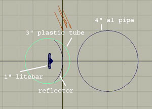
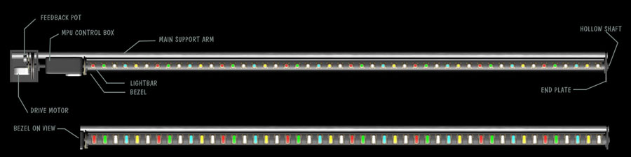
| I know, I know, it looks really complicated, and probably will end up looking very different from this picture, but one has to start somewhere right? These LED's are 3 watters so need to be mounted on a heat sink made from aluminum angle or flat bar. The cool thing about LED's is they can be over powered momentarily to get almost twice the brightness, which is perfect for a stage light show! I propose the bar (lighted area) will be 48" long. It was going to be longer, but then packing it around would become an issue. I could always make a second if I need more. | |
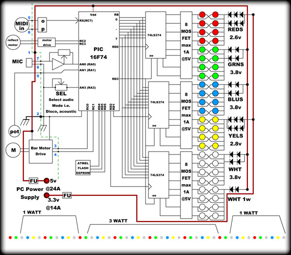
| CIRCUIT DESCRIPTION: The power consumption is something else at these low voltages. I plan to parallel the LED's in pairs which will allow a pulsed supply of 5 VDC to work with it. A desktop PC supply that can deliver about 30A @ 5 volts will be fine. ( and cheap! ) ...also because the color lines would be 32 otherwise! Too many for a wash light. I have already drawn up 3 different schematics, but have found this one to be the best. Note only 24 lines go to drive the LED's. The last design had 48, when I realized that's a lot of wires to fit through the hollow shaft the whole thing spins on. Also programming for 24 is less complex. I have
found some MOSFET drivers that are way over-rated, just to be safe, but have
a small case size so lots can be fit into a small box. At $.55 each ($.42 if
you buy 25) they fit the bill financially as well. The 74LS374's ( octal latches ) are being used to free up some pins on the PIC microcontroller. The bus will be updated at the PWM period / 256 in sequence, which isn't an issue as these chips are fast. The "oe" on those is Output Enable, and can be used to easily blank the LED's from software, without effecting the individual PWM counts. This may be useful for halving the brightness or overload conditions etc. I may add a decoupled drive circuit so if the PIC hangs, the LEDs go out. The EEPROM is a recent addition. I decided it'd be cool to use a MIDI sequencer to program lighting sequences under a 2 note identifier to recall them. This way, it doesn't have to be manually controlled from every song I create a MIDI sequence for. I like automation, especially on stage, and this is automating an automation, so I really like it!! (Update: Used this on the StripLights, works great!) The motor drives will depend on DC motor or stepper motor. The second motor is to control a bezel that comes around 180º that has a magnifier in it. (Top image lower lightbar) So the light can be a wash, or a focused bar, say, 15º wide. Because the light bar rotates right around, the audience can be flashed as well. |
 |
|
There is a pot that is tagged "SEL". This pot will enable manual selection
of different preset sequences. Perhaps Club modes, Acoustic modes, Disco
modes etc. The feedback will be the LED's when selecting. This will effect
how the Audio automation will function. i.e. in Club mode, Low frequency
beats will trigger timing on the sequence. In acoustic mode, signal level
will trigger change in lighting colors. In disco mode it may be a
combination beat/frequencies/levels. The other pot is a feedback voltage from the shaft, so the PIC knows where the thing is at any given moment. I've designed this type of system before, and it needs *some* intelligence, but overall, it's pretty reliable. Apart from the mechanics of the whole thing, this project shouldn't be too hard to do. (Famous last words haha!) As the project gets under way, I'll update this page! October 23rd 2012 |
|
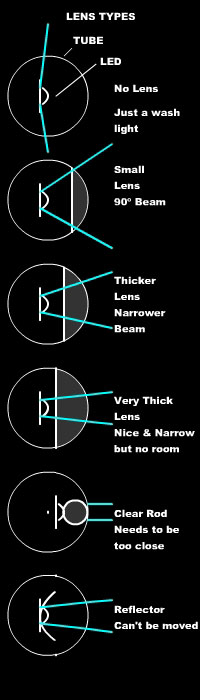
| As with all wonderful ideas, seeming so simple and eloquent to begin with, something always throws a monkey wrench into the works. The monkey wrench in this case is lens focal point. | |||||||
 |
|
||||||

|
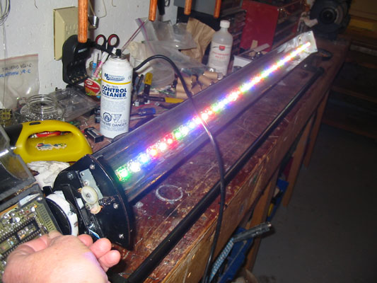
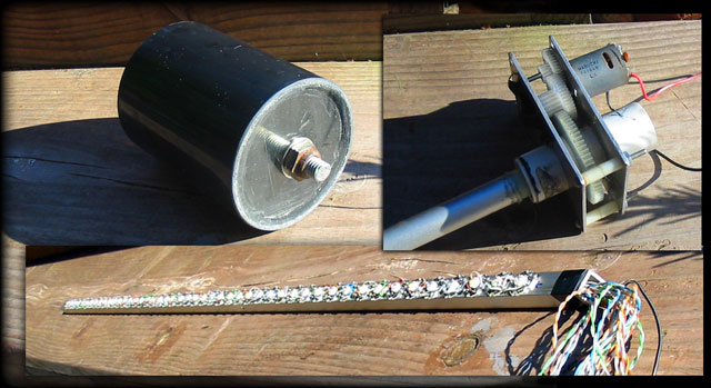
Update March 2013: As you can see, the project has gone from paper ( well PC paper ) to reality at last! I wasn't in any big rush and I had a number of other "more important" projects to do before this, but now I'm free to dabble. The LEDs are spaced 15/16" and there's 48 of them as promised, so that makes the LED's 42" + ends (3" * 2) = about 48". |
|||
| I made it
this size because things tend to come in 4' strips. Screwing in 96 little
#4 screws was a bit of a job, but the heat sink compound is down and the
wiring is done! Unfortunately I had to strip the cover off of the nice
stranded CAT-5 cable I found at the scrap yard or it wouldn't have fit
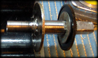
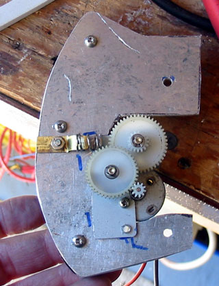
into the bar near the end. 42 wires, Pretty packed! The gear box was made from a couple pieces of aluminum plate, and I used some nylon gears I had...against my better judgment. I always swear when they fail, but here I am using them myself. The shafts should have absolutely no play, but the big gear wasn't centered properly ( came that way! ) so I had to allow the center gear to wobble a bit. It works fine even off of a 1.5 volt C-cell and has quite a bit of torque. I went with a DC motor which can be controlled by PWM type signals on a MOSFET and DPDT relay (instead of a complicated 4 MOSFET H-Bridge) This will work as long as a few mS are allowed for the relay throw/release period before applying power through the MOSFET. (No sparks!) |
 |
||
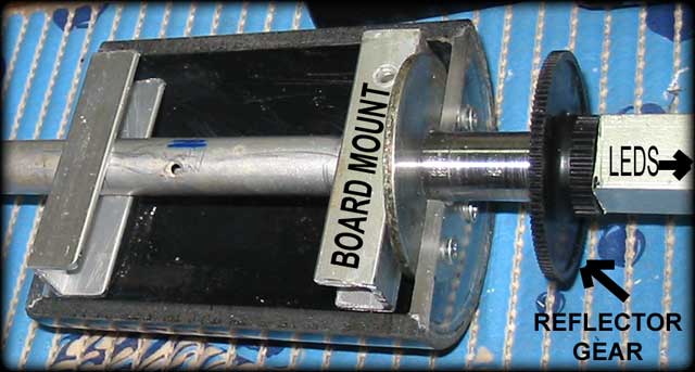
| Next I made the "box" that will house the PC Boards. That's the round drum-thing. I was going to go square, but looks are important right? I've split it to open, and will put some hinges on one side and a snap catch on the other. I've learned over time to make it as easy as possible to access the circuitry. This is as easy as it gets because it doesn't matter which way it sits inside. | |||
The board mounts stiffly rotate to make it easy to get at either board. The wires will feed from the bar into a steel coupler shaft made from plumbing pipe, then into the aluminum drive shaft and out of a hole cut in the side.
The only problem I have with this is the motor wiring limits how much the reflector can turn, so I'll have to add some sort of mechanical stop to prevent wires getting wrapped around and around. The reflector is going to be a big buffing job, and perhaps a bit of welding. I've never welded aluminum before so it'll either work or be a total disaster lol! We'll see. |
 |
||
|
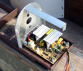
Another change was deciding to mount the PC power supply inside the drive
unit. Sure it'll make the whole thing bigger, but I like the idea of just
plugging in a power cord with no big messy box next to it cluttering up
the floor. I will be taking the power supply out of it's original box
though, so it's just a board and fan. Well that's about it for now! I'll post again soon. Cheers! |
|||
 |
|
| Update: April 4th 2013 | |
|
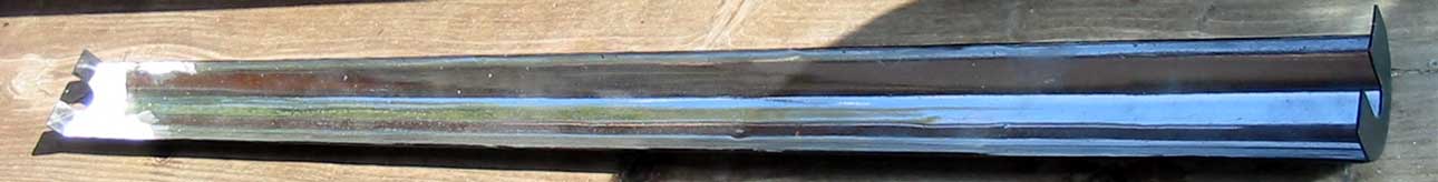
Finally
I worked up the courage to cut out and polish the reflector! It's just
less than 1/2 of an aluminum pipe I carefully jig sawed then welded end
plates on to. I've never welded aluminum, but this worked out ok.
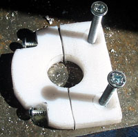
It's not very heavy, about 1 lb, but I'll still need to counter weight it. The little gear assembly came together nicely. I don't know what it was originally, but I managed to find a motor with a proper size gear in my junk box. The whole plate pivots, spring loaded, just in case the reflector drive gear is slightly out of alignment.
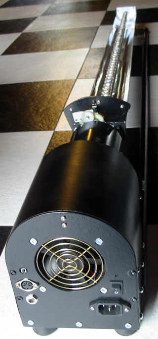
I had mentioned the power supply will be built in, so that dictated the minimum size of the box. I had to use a PC power supply because of the large amperage, but if it ever blows, the form factor for these is pretty much the same so a replacement would be easy. The tall image to the extreme right shows the whole unit all together. I did some tests with a 1.5 volt "C" cell on both the drive & reflector motors and it turns nicely and slowly. With 3 volts it turns pretty quick. I mounted a 10-turn pot with a gear off of the drive motor's 2nd gear, which will be the position feedback to the PIC chip. It allows for over 2 turns and I didn't use a stop pin (although I still may add one to the reflector) because it must be used on the floor, or the ceiling. Thus, the drive will be shifted be 180º. The reflector will only have 4 positions, so I drilled 4 holes in its main gear for an IR LED/Sensor. I decided to mount the reflector drive motor on the reflector which means it can only turn once, but it is nice and solid. |
|
 |
||||
|
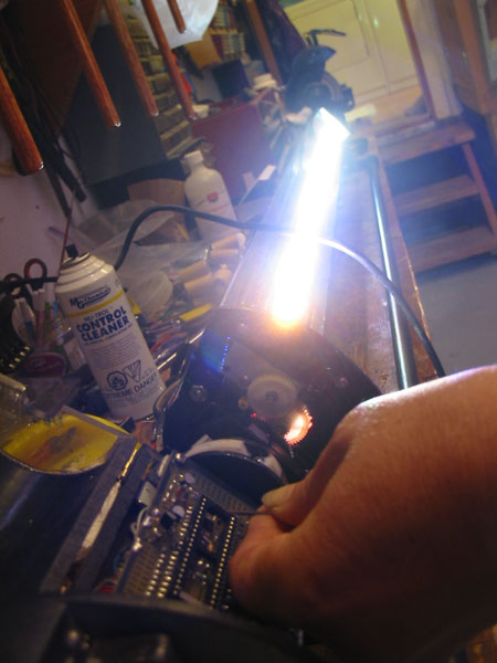
Now the
mechanical side of the project is complete, I'll be moving on to the
electronics. Almost all of that must fit into the round case on the
shaft, so it'll be a challenge to get it all wired on. Oh! The 50 (was 42)
wires just barely fit through the shaft to the light bar! Cheers * |
||||||
Dec13th 2013 Update: |
||||||
|
Disclaimer: This is not an
instructional page to build or manufacture the above project, nor are there
any guarantees of accuracy herein. This page is an "of interest" discussion, and the project is intended for my own personal use. If you have any questions, or wish to pursue this project, you may contact me (Sandra) at fresh(at)freshnelly.com |
![]()