|
SDS Wi-Par 40's by Sandy Sims |
||
 |
||
|
SDS Wi-Par 40's by Sandy Sims |
||
|
|
||
These lights will be
the ultimate in convenience for a quick setup!
One Red/Warm White, one Green/ Cool White, one Blue/Cool White
Just clip 'em on, plugg'em in, and light'em up.
BTW No batteries makes them light as a feather!
|
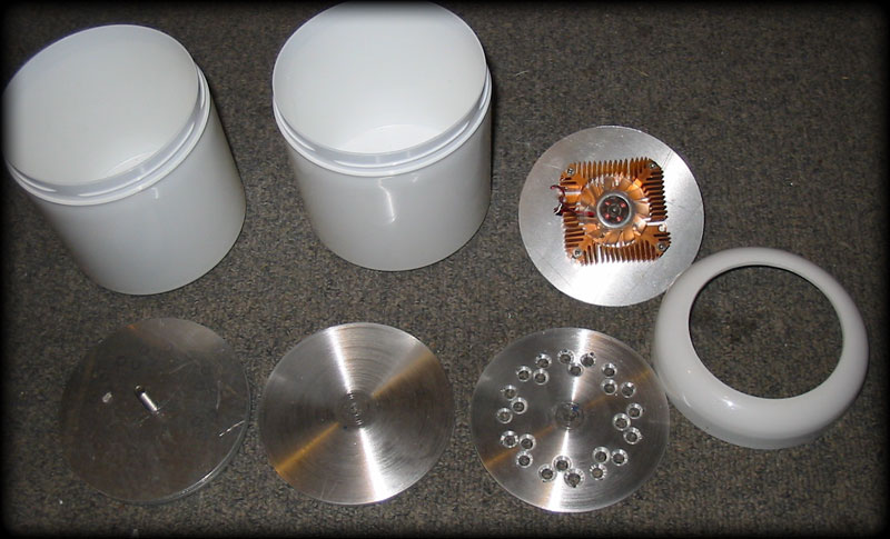
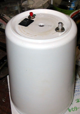
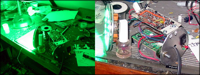
The above photo shows the prep work for the lights. The little fan(s) I
got on eBay for next to nothing should be able to keep things cool. The
bottom plate aluminum (I spun on the lathe) is almost 1/4 " so hopefully
thats enough to rid the LEDs of their heat. The one in the center looks
rather like my "platinum CD" I'm getting ready to release LOL. Anyway, all that is pointless as it turns out. These were "chosen" for the project when I had intended to use low-voltage wire running to each can, and have the main power supply in the control box. I started to think of all the costs and issues this approach would create:
- Heavy wire ( big
enough to handle 5 amps ) would need to run up/along/under
ceilings/carpets/chairs/walls etc. and would therefore need to be pretty
long to reach to the stage area where the computer/keyboards/amps and all
my other stuff would be. With all of that above, I've decided to make them wirelessly controlled. This solves all of the problems but creates some new problems:
- Now each PAR unit
needs it's own mains power supply.
|
|||
|
OK so
there's a few issues with the case size. Fortunately, when we sailed down
to the US we bought a few cans of (unbelievably cheap!) tobacco and
kept the cans on board when we came back. These cans are the same 4"
diameter but are a good 2" deeper! Unfortunately the lids I've cut out
don't fit those (American thread I guess haha) so I'll have to cut the
"new" cans' lids. No I just need to talk Gena out of them as she's using
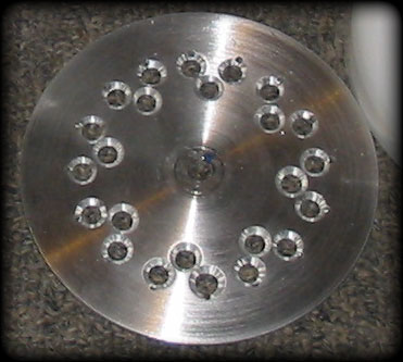
them to store large nails in right now! The layout of the holes I've drilled for a light is better explained by the diagrams below, but the main intention is to have 16 3 watt color LEDs, and 8 white (warm or cold depending on the color with it) The 16 color LEDs are split in half so one side can be turned off (mostly for dance-light FX) which, when hooked 8 in series will take 23 - 28 Volts appx. to fully drive. The inner holes are for the 8 whites. This is so I can make pink, light blue, and light green without using the other 2 cans. All PAR Can's LED's will be PWM controlled via MOSFET's and should have variable speed fan with thermal sensors to lower the brightness in the case of a fan failure etc. overheat scenario. The next issue to tackle is the method of wireless. I found several different modules on eBay (from China) but couldn't decide between the simple AM 318 MHz Transmitter/ Reciever boards and the complex wi-fi bi-directional SPI type: 318 MHz AM
modules: 2.4 GHz Wireless
Module: SO with
that I bought a bunch of each, which cost me a whopping $8 for 5 wiFi's
and $7 for 6 pairs of 318 MHz's. $15. :) |
|
||
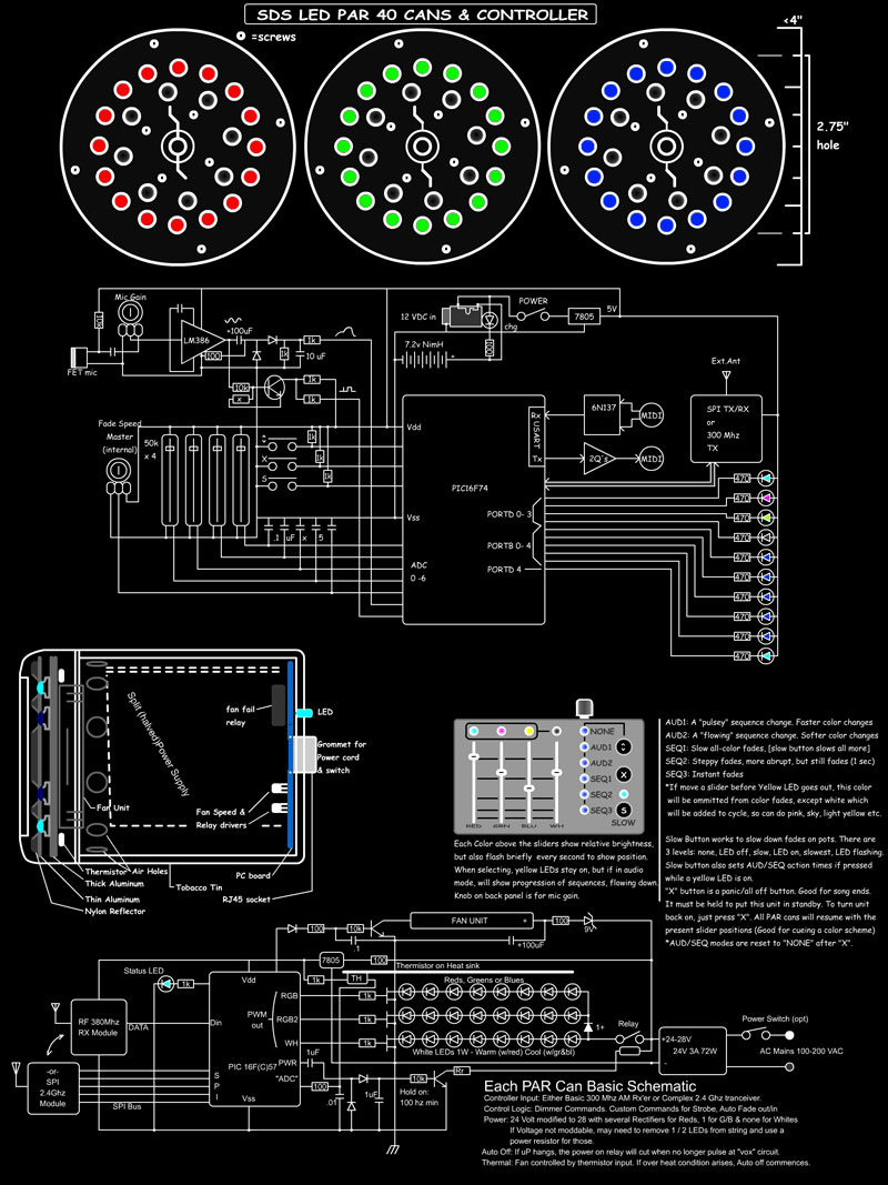 Proposed Schematic: Sorry it's a little bit small, I'll post a bigger one once underway as it'll change I'm sure. Just keep in mind as well, this smaller image consumes less internet bandwidth than the bigger one I have, so it consumes less energy, and if the server is running on power produced by a coal fired generator, and 1000's of people look at this image instead of the bigger one, then think of all the CO2 we DIDN'T put into the atmosphere! You've done your good deed for the day, and Thank you! |
|||
|
Update Dec 28th 2013: Now that I don't have all of the running around/performing/shopping to do that the holiday season demands, I can get back to the project!
|
||||
 |
 |
Once firing up the greens commenced, I, and my partner Gena were momentarily "blinded by the light!" Wow is it bright! SO I guess worrying about over heating isn't suck an issue after all as I'll never leave it on continuously. I guess it should be bright as the greens total to 48 watts, which translates to 240 watts incandescent, if green incandescent bulbs worked for crap, which they don't. It's a beautiful thing, can't wait to do the blues & reds! With the fan running, the preliminary thermal test (my finger on plate until too hot!) demonstrated about a 70/30 cycle i.e. on for 20 seconds, off for 8 seconds. The LED's can of course get much warmer than that, but I'm somewhat concerned about the plastic housing. If it was really important the housing could be made out of aluminum, which would solve all heat problems, but I don't want one falling on an audience member and killing them! While performing, these lights likely won't even be at half. Apart from that, mostly the lights will be flashing on and off to dance music etc. in which case they can go full on. |
||
 |
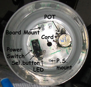
The board
will mount off some angle attached through the plate via 2 self tapping
screws (so it can be pulled out without pulling the whole thing apart) and
will house the PIC chip, MOSFET drivers, and other circuitry, as well as
the 2.4Ghz wireless. Yep! I'm going with it. The pot is one of several large 1 Megohm pots I've had laying around, so I might as well use some. The switch will turn off the AC Mains so as to avoid a "vampire" power draw when not in use. I've added a select button in case I want to control modes if in stand-alone operation. The LED will indicate power and then RF Link status by flashing if no link. As can be seen, there's 16 Greens and 8 whites. At 30 VDC this brings the LEDs close to their max. voltage handling: 30V/8=3.75V per LED. |
|||
|
Circuit updates: * Knob on back: The 1 Megohm pot that's bee added is for manual control of each light in case the controller isn't present or working or whatever. The pot will "take over" but if a controller control is moved, the controller will take over. * Select Button: This button will allow for test mode, lighting modes, reset or whatever else I think up. * PWM shutdown: If the PIC chip freezes for some reason or other, (rare) an NPN transistor will no longer be powered by a decoupled pulse train from the PIC and will therefore release the relay which will shut down the LEDs. I hate using relays, but I guess this is the safest way. * ADC Circuit: Because I am using these under-powered PIC16F57's to get rid of them, and they have no ADC peripheral, AND I'm using a 1 Megohm pot, I must make a "special" ADC circuit. It's basically an RC network whereas the cap is pulled high, then checked to see how long it takes to discharge through the pot. Because this is such a high value pot, the cap will need to be smaller than usual, depending on the timing of course. The SMD thermistor (10k room temp) will be more standard, probably a .022uF or .01 cap.
Notes: I've decided to hand draw the boards, well at this end, then photo-etch the controller board. I think the most difficult part of the programming will be interfacing to the wireless board, and this PIC doesn't even have an SPI peripheral! Wish me luck ;) **Note: Please don't start building this if you're planning on it! The schematic above may change 3 times before I finally finish!!
|
||||
| Update Jan 14th 2013: | ||||
 |
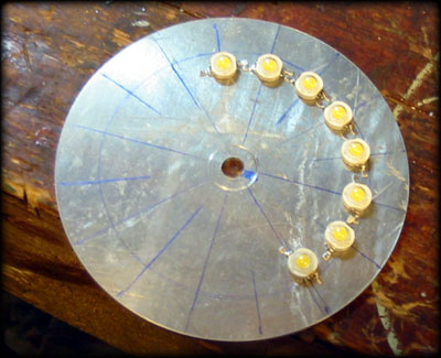
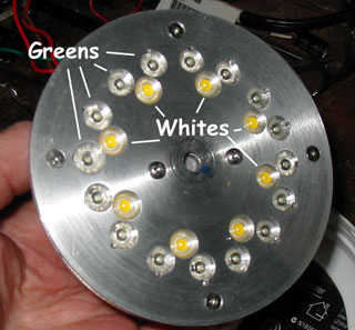
There's
the first first Can under development. (Photos left) and a test run with
the dimmer pot on the back panel. I bet you can't guess what color it is? I'm still in awe how pure and bright the color is! The thermal sensing and fan cut-in etc works great. I have "over-heated" the thing several times (Greens & Whites full on) and the auto-dimmer works great. The delay is over 8 seconds from full to.. not full, and really, it's very hard to notice that it has happened at all, which is good! The button now selects what the pot is adjusting, green or whites in this case, so both can be mixed and tuned as a stand-alone. I had to speed up the PWM period to 120/second as I could still see a flicker, and I really don't want to use caps to smooth it as that will be problematic with "strobe" mode.
|
|
The button, if
held for >1 second, also selects 1 of 4 auto fade modes. These modes are: - fast rise/fall of green (8 seconds) - slow rise/fall of green (20 seconds or so) - fast rise/fall of green and white, about 90º out of phase, and - slow/variable rise and fall, randomized speed variance from thermistor ADC reading. This is so each can can be different from other cans in this mode. I may call this from controller too! |
|
| I have
been really busy with other things since the year began, so my programming
for the "radio" part has been slowly advancing. Because of the crappy
abilities of the PIC 16F57 ( I am almost out of them, yay! ) I've
discovered that in order to maintain a smooth software PWM to the LEDs
( 1/120th sec period, 32 uS/step ) the SPI routine must be embedded
in-line with the program cycle. To make matters worse, I can't even send a
full byte across the SPI within the remaining 12 uS I have left of the 32
uS. So SPI clock speed is 32 uS! That seems still fast, maybe by Arduino
standards, but an SPI transaction to unload 16 RX bytes will take a
whopping 4 ms!
Of course most of the messages will be shorter, and even 250 changes per second isn't too shabby for controlling a single par can! Anyway, the decided protocol is logical, allows slow fades, fast on/offs, strobing, and good RF channel control. More on all that later! After
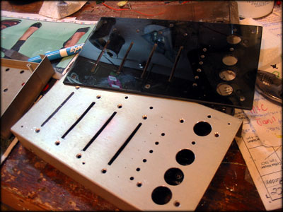
getting tired of programming, I started on the controller case. I know
this is jumping the gun, but eventually it needs to be done, so while I'm
in a more "physical than mental" mood, out came the saws, drills, and
grinders. Once that part was finished without destruction, I merrily went along drilling holes big and small, some just in the metal box, others in both the plastic, and the metal box. The aluminum box was picked from our local scrap yard a few days ago. It was some sort of C-band sat mixer or something like that. It's so totally amazing what people throw away! The big white buttons are from a telephone my neighbor gave me, see why I like big round buttons? Easy to drill for, I'm always on the look-out for them. I'm trying to decide on whether to use the rubber switch pads or real switches yet. I have since sanded off their numbers and put on new designations and some clear coat. (Photo Collage Below.)
|
  |
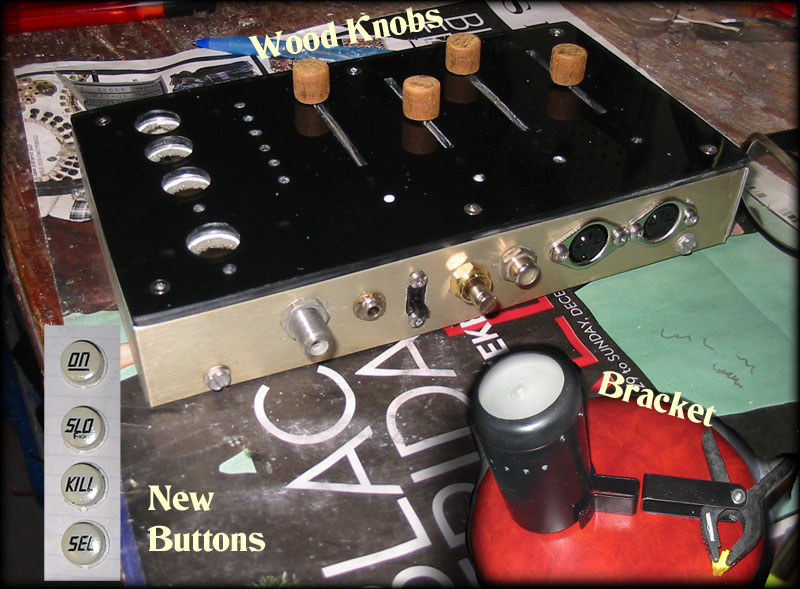 |
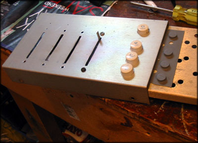
Oh! and I
have made a fancy mounting bracket for the first can! It's pretty skookum!
Hope I can duplicate it 2 more times haha! The back panel shows antenna receptacle, for longer range, power socket, power switch, microphone gain, extra output (phono) for DMX or whatever, and MIDI in/out. There's the buttons done, On takes out of standby, Slo is to set to slow-fade mode (hold to adj speed with a slider), Kill is for sudden all off without loosing pot positions, Sel selects the different Auto-play modes. I think the wood dowel Flintstones knobs are a nice mix of hi-tech with old school wooden component electronics, but more so, I just don't have any slider knobs. ...maybe I should've made wood buttons too...naw! lol Ok well that's about it for now. |
|
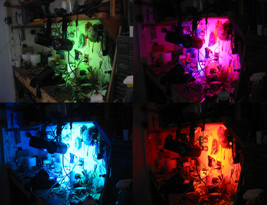
Update: Here's some color tests using all 3 wipars. The green is a partial mix of white, the pink is red and blue with a bit of white (or it'd be purple), the blue is mixed with white, and the orange is 2 parts red mixed with 1 part green. Intially I had problems with the wireless range, but after adding a proper antenna to the controller, the range is at least 100' now. If the cans had antennas, the range would be 3x that I'm sure. Problems! So I'm thinking of putting in normal fans mounted over the heatsinks. As a result of these stupid fans I've accidentally cooked out some of the whites on the red par can, then a couple of weeks later the green's whites went out. The others are ok, but I know it's because of the fans. If I had to do this again, or your planning on doing it, I think it'd be best to use large aluminum pipe with the ends bracketed and screwed in place with aluminum blocks, and the fan ( a real fan!!) on the back. |
 |
| Here's
the final look of the controller. I know I kinda got carried away with the
graphics/stickers a bit, but what the hey, it's a fun toy to have...and I
love stickers! The auto-sequence/fade modes work well with audio as long as it's sufficiently loud enough. The Auto-Play modes are all influenced be the microphone. Adjust Mic gain pot (on back) to get the best effect.
The 6 Yellow LEDs
show which auto play is selected (or off) as follows.
It has NiMH
batteries, (cheapo's) so can only run about 2 hours on a full charge. They
are charged using an in-line flashing LED so can be left plugged in all of
the time without worrying about charge monitors and such. The user manual is here if you want to check it out or get some ideas for your own endeavors. Eventually I'll post some video of them in action, which be listed below this. |
 |
|
Yay! Video! So now you can watch them in action, and get a good idea of how the Strip Lights (to be renamed "Light Strip" because of obvious connotations!) work as well. The Strip Lights are "aware" of the WiPars through it's filtered photo sensors. And I can see the interaction. The WiPar's strobe speed is adjustable and has been slowed some for the video or weird stuff starts happening. Enjoy! |
|
|
Summary: While this was a great project for learning the protocols and implementation of wireless, it was very tricky to set up. If anyone out there is thinking of using wireless / bluetooth in a project, you really should consider using Arduino's, not PIC. The libraries already exist for Arduino, which would keep the "fun" in playing with wireless. Modern wireless comm. is amazingly powerful/versatile, but setting it up is extremely complex (and seems like a lot of work to save a few feed of cable) to the point it almost turned me off of doing the project this way. The MIDI control works wonderfully, and reliably as long as the connection is solid. I always fear the "note-on, but no note-off" scenario. Because these are bi-directional, "all notes off" could be sent in the event any notes are on at the time of a disconnection, or a data table could be mapped to identify what kind of instrument is playing (piano, strings. drums, koto) and decide on appropriate action if signal is lost (at the receiving end). For example, a piano is a one-shot sound, so a skipped note-off wouldn't be a catastrophe, strings are slow fade so could be left on for a few seconds, a trumpet would need to stop immediately, drums are pretty much 1-shot so could all be cut. |
|
|
Disclaimer: This is not an
instructional page to build or manufacture the above project, nor are there
any guarantees of accuracy herein. This page is an "of interest" discussion, and the project is intended for my own personal use. If you have any questions, or wish to pursue this project, you may contact me (Sandra) at fresh(at)freshnelly.com Project Copyright : Fresh Nelly Musik |
|
|
![]()