|
Problem:
After using a piezo tap pedal live, it became apparent that I wasn't
always going to be able to concentrate on keeping my foot on the flat little
pedal, play, and sing all at the same time. I did it, but a couple of songs
were monkeyed up because I was trying to find the silly pedal that, despite
my best efforts with no-slip and silicone pads, still managed to move around
on the cornmeal floor (or whatever it was!). Once I was sitting which is
generally easier, but I was wearing a long skirt and I couldn't see where it
was, so I hiked my skirt up mid-song in a desperate effort to find it
and got cat calls from the audience (blush!)
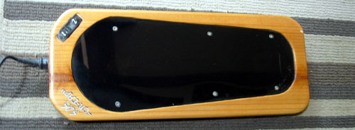 |
I
made a new pedal with edges shaped like a shoe sole (shown in photo
left), so my foot is always "in" it. It works good and has a
separate sensor for toe tapping, but still my foot moves off of it and I
don't feel it unless I'm barefoot.
Gena, my partner, told
me I should make it strap on like a ski, or maybe a sandal, which is a good
idea. But really, I might as well make it a shoe after all that! |
A Real Solution:
A while back I saw that some guy had made a pair of MIDI shoes that had
piezo's built right in, and a wire coming out of each shoe to plug into a
V-Drum set. That gave me the solution to this. A well placed piezo embedded
in the heel (and maybe on e in the toe) would mean I could be anywhere on
stage and it'd work! Right away the wire must go. With all of the tiny &
affordable ($3) wireless boards out there, wires are a real no-go with me.
Of
course this greatly complicates the whole thing. A battery is needed, a
transmitter, a switch so the battery doesn't die, a socket to plug in a
charger to charge the battery, an LED to show it's on, and a dedicated
receiver to decode that a "tap" has actually happened. (Built inside the
Show-In-A-Box case.
I bought
some used ( but nice ) shoes that have a bit of a clog height, about an
inch, and tore it apart. To be light weight, I know shoes aren't solid
rubber, they are hollow with supports, usually triangular in shape,
throughout. I was right. I don't want to weaken the integrity oft he shoe,
especially being it's for stompin', so the boards must fit into the deep
triangles.
A 318Mhz TX
with Rx'er is definitly tiny enough. I found a flash PIC in my stuff that
only has 8 legs, but fits the description of what I need here. I've ordered
7.6 V worth of LiPo Batteries already but they haven't arrived yet so I
guess I'll have to wait.
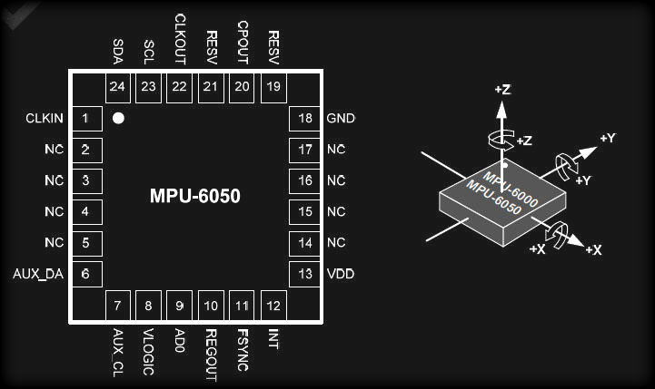
What
did arrive was a curiosity item I purchased about a month ago. An MPU-6050
accelerometer / gyro chip. I've played around with accelerometer chips years
ago, but this gyro is new to me. Back in the day the accel. sent out tiny
x/y/z voltages that required the amps to the ADC's to be right next to the
chip in order to get a stable usable reading.
But since the advent of tablets and phones and cameras using them for
image stabilizing they have really evolved. And thankfully the price is 10%
of what it was only 6 years ago!
|
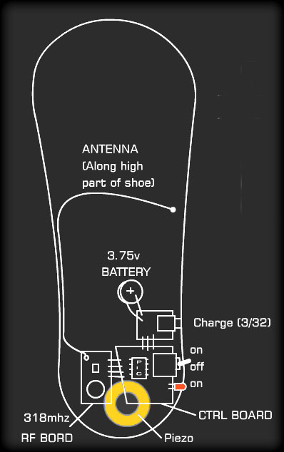
The original "no frills" idea...
|
 |
It's remarkable
how many things this could do, and how precise it could be. I can change
the "dummy" data stream originally to be transmitted into a real one
that can carry position, tilt, roll, and of course shock data.
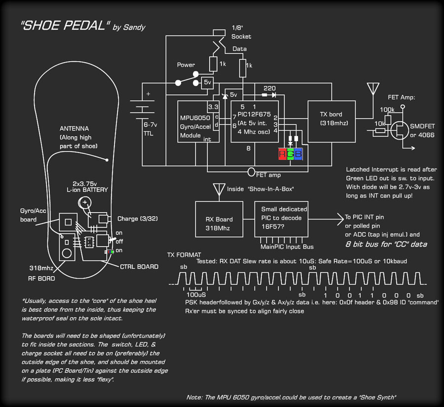
The new
diagram to the left describes the new layout. (No I KNOW I'm an
engineer! ) No project is complete without an RGB LED, and I had to
sacrifice for it as well.
The Circuit:
The MPU6050 board has it's own 3.3V regulator so 5 volts is fed to it from
the 5V regulator. The TX board is also 5 volts so is on the same bus.
The Clk & Dat on the I2C bus must have resistors. The Clk can be a 3.9k &
10k to Gnd on low side to get 3.3v. The Dat must be bi-directional so is
just a 3.9k. The PIC12F675 will provide a weak pullup for rx'ing data
from the MPU.
The "3" LEDs are driven by
3 ports, 2 of which are used as inputs as well. All 6 pins are GPIO.
Green: I have the INT output from the MPU marked as amplified,
but using a diode on the LED will allow a weak pull-up to do it's job.
Red: Shares a pin (5) with a serial data input from the charge
plug. (Must be a stereo 1/8") The zener will stop the surge of power
when plugging in to charge.
*If the pin is high on power-up, will switch into programming mode to
change settings via 9600 baud.
Pin 2 sends pulse
data to the Radio TX'er. This will be in PSK non-standard, works good if
signal is good. This TX'er is one way of course, but the "bootstrap
antenna" (hahaha sorry!) should give a few feet of range.
The batteries will only
charge when power switch off. |
The MPU6050 is a fairly complex beast, but it shouldn't be too hard to
deal with once familiarity kicks in :)
Thoughts
on usage:
For different modes, the control must be on shoe-pedal itself:
Hold foot vertical and tap heel to turn on/off tap function: led goes Green
or flashing(off) *turned off by next..
Hold foot sideways and tap on side to switch in/out Note mode (like tapping
toe on a circle of music keys!):Led flashes Red
Hold foot toe-down and tap toe for another mode....
Update:
The radio transmitter/receiver will still be the same, but I think the
microcontroller would be better an Arduino pro-mini. It'd be able to handle
the switching and LED easier, be easier to program, using a different plug,
and end up more configurable. The best feature of using the pro-mini is it's
built in hardware USART.
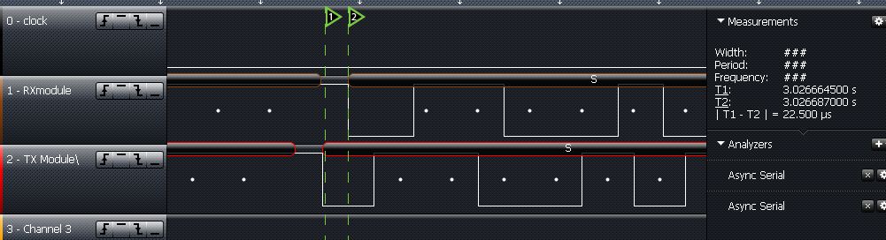
USART
Radio Test:
The first test was 2400 baud and worked flawlessley, then up to 9600,
then 19200 baud (plot shown right). You can see the slight delay (as a
result of the slew mentioned above)
I was
really surprised this even worked at all as with radio PSK, FSK are
king. I'm still not entirely secure with this method as 15 feet away
errors started, and at higher baud rates, the slew delay (I wish I could
fix that!) starts causing errors.
You can
see how that would happen in the lower sample. Hi-Lo is only 22.5uS, but
the return to Hi is almost twice that.
It seems
stable at 19200 otherwise, and generally I won't be much further than a
few feet from the SIAB. This test also used pretty crappy non-tuned
antennas, just bits of wire off the wish board. Because the antenna is
90% of the system usually (well 100% if it is disconnected!) I'm sure
the range will be much better.
|
 |
|
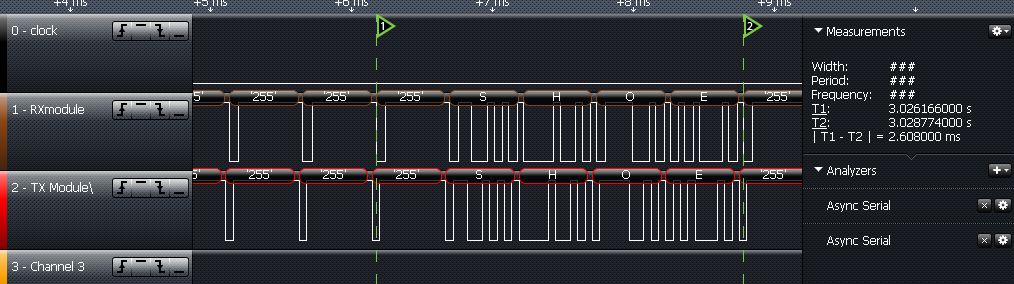
The '255's
are to establish a stable sync and carrier. To conserve battery
power, a shutdown of the stream would be desirable, but the "header"
required can be slow. A time delayed stop transmit may work. If
there is no motion for a minute, then the transmit stops. But that
may become a problem as well!
The
best solution was to find a maximum time that the transmitter would
stay active, and keep the RX USART happy. The TX module uses
decoupling caps, so once the cap is charged, the TX stops. Therefore
the maximum time for inactivity is 30mS (as tested) so it'll be 20mS
to stay inside the safety zone with '255's, which are only a 1/10
byte pulse.
The
logic analyzer output to the right shows it's all pretty stable. (TX
is red) Me likey! |
 |
Future
Modifications:
I know I won't be able to leave it at this, as one never can right?
Having holes drilled in the side of a rubber sole of a shoe is a
recipe for disaster, especially in the wet climate I live in. One
puddle and it's done! It needs to be sealed.
The charger/Programmer is the big problem. It's very preferable to
have a socket to plug into for that, which would prevent
repeatedly pulling it apart to plug in the programmer.
The charging could be done with a simple inductor pairing (you can
actually buy those now!) by way of using two coils at resonance, one
in the shoe, the other on a charge station. By oscillating the
charge coil, the power will transfer to the shoe coil. This voltage
must be rectified of course, then regulated to charge the battery.
|
The
programming (FTDI) could be connected via a small header on the
top of the shoe (somewhere..?) Once the programming is done, it
could be tucked under the sole into a spare opening for safe
keeping.
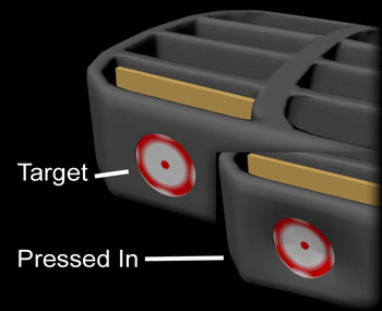
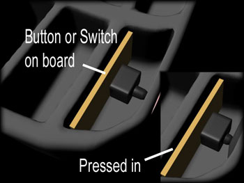
The switch (push-in, push-out, or just pushbutton as Arduino
could standby in low-draw "sleep" mode) could be mounted on a
small board on the back of an opening facing outward, then it'd
only take a push in the rubber side to "click" it on/off.
I made
a little CG drawing of the heel area and how this would work (in
theory!) to the right. It's pretty flexible on the sides (the
heel) between the gussets.
The
RGB LED could be a fancy affair. Adafruit and their "wearables"
comes to mind. What's wrong with a few twinkling LEDs at foot
(sorry haha!) They *are* pretty so maybe I'll run them over the
top or along the edge. We'll see! |
 |
|
OK that'll be
it on this part of the project for a while, as the whole SIAB box has
priority over this.
|
More to come!
Cheers! Sandy*
June 17th 2015 |