| Dash Rudder ind. & dimmer control |
 |
A good solution to 2 problems! |
| Dash Rudder ind. & dimmer control |
|
A good solution to 2 problems! |
| As we have a hydraulic system for
steering, it is especially important to know where the rudder is in
certain situations. Some rudder indicators are straight meters, other
fancy ones can be LCD, LED, or incorporated into an auto pilot display.
The problem is, they are damned expensive. Even the "pot" sender unit we acquired on eBay is over $400 new! That's not including the display. We do have an auto pilot, but once again, the power consumption is substantial if left on for extended periods. Most of the equipment I am building for the boat is due to power concerns. No wonder so many people must run their engine, or have a genset on board to keep the batteries up.
|
|
| The flash schematic below is the design I came up with to combat the battery battle. The main chip is ( of course ) a PIC16F57 microcontroller. Not only does it indicate the rudder angle in 5º segments, but is also the dashboard dimmer controller. | |
|
|
|
| All of the bulbs in the dash indicators
have been replaced with red LEDs in order to prevent night blindness. We
talk to many truckers in our business on the subject of dash indicators
and radio bulbs that are green causing loss of night vision. The old wind indicators are sealed so we couldn't replace their white lights. Special circuitry and programming was created to control these in relation to the LEDs ( which require less voltage and have a different brightness curve ) Preferred operation: 1) The dimmer control on the switch panel
raises and lowers brightness level of the dash panel, and the LED bar
for rudder indication. This utilizes a 3-way rocker switch with spring
centering. Circuitry: The Xtal running the PIC is at 16 MHz although not crucial, it should be around that. The 3904's are good to about .5 amps but will only drive 3 bulbs that are 50 ma each, and 14 leds with 2 k resistors on them. An hv style "light snake" is behind our switch panel, probably from a Bayliner or such. I know it can be dimmed and doesn't draw anything for mA's but can't say for sure which it should be hooked to. The bulb (C3) or the LED driver (C4). -Rudder The rudder sender, a 2k potentiometer basically, sends a voltage centered preferably at 2.5 volts. The top tap is 5 volts and the bottom is at ground level. Because the auto pilot both taps from the center arm of the pot, and powers it, rectifiers have been used to isolate the +5 volts from each other. This means the 7805 regulator output must be raised by the same voltage drop so it will supply 5 volts after the rectifier. This is accomplished by adding a diode on the ground side of the regulator. The auto pilot will suffer a similar modification! The center tap voltage is then fed to a
single LM324 op amp. This is to balance the gain vs. centering of the
voltage. The output from that op amp is fed into another op amp
configured to be an ADC ( analogue to digital converter ) through the
programming in the PIC chip. AS the .01uF capacitor discharges, the PIC
counts how long it takes and calculates the voltage using the RC time
constant. As soon as the op amp crosses the zero mark, the output
switches and the count is stopped. -Dimmer The bright/Dim switch is scanned by the PIC, incrementing or decrementing the pulse width of the output transistors. The wider the high pulse, the brighter the LEDs/Bulbs. The bulb width has a cutoff around 33% as it will go out before the LEDs are fully dim. ( Done in the programming ) The CDS cell is measured via ADC ( similar to above but with resistance ) then compared to the threshold preset. If the CDS resistance is lower ( brighter ) then the output transistors are shut off, and the pulse to the 74LS138's is set to constantly on. This gives the rudder LEDs max brightness for daytime conditions. There is some delay to prevent threshold reflective oscillation due to load variations etc. -Other The I/O at ports C0 & C1 are to communicate with the DashPIC box, which communicates with the pedistal display and PC. When unit first powered up, it requests CDS threshold data from the DashPIC which is always "waking up" or on. If the request times out, it is made again a few second later. -------- |
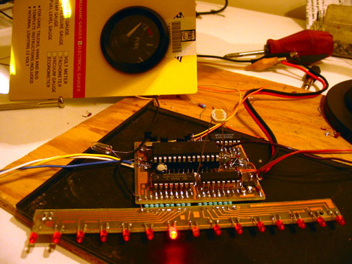 Tests |
| Here's 2 photos, one
with low dimmer setting, one with high. The bulb is to emulate the bulbs in
the old type wind instruments. The fuel gauge is LED ( flux-red). The rudder
indicator has the very dimly glowing position indicating LEDs as a
background. This was a 1/256 width cycle! The photo above is under incandescent light. Notice the threshold has been passed as the bulb and gauge are no longer on, while the LED bar is at max. So far so good!
Below are scope readings on the ( single ) pot from rudder. Notice the cap charge time isn't linear. This is why only a portion of it can be used to show linearity. I may change the length of the pull down pulse as I have recently remembered that a 5:1 ratio on a capacitor yeilds "near" total disharge. The overall speed of the routines isn't important as it is far above the visual "flicker" level. ( The speed the LEDs would flash that the human eye would start to notice oscillation -which, to me is very annoying! ) The 3 below are of the CDS ADC capacitor during different light levels. These readings are all on the same time scale. The daylight to light bulb levels are fairly close, while the dark level is very long. That is because our perception isn't equal to that of a CDS cell, so the curve is not at all linear. Because this is a threshold that involves lighter than dark levels, it's not a concern. If it were, a very large count would be required, say, 2 bytes instead of 1 (65536) The step speed for the dimmer had to be
modified as well because the "dim" end would take for ever and the bright
end would zip by too fast to let go of the switch in time. I made it step in
direct proportion to the pulse width count. All in all I think it takes 12 seconds from very dim to very bright. |
 |
 |
|
 |
|
 |
|
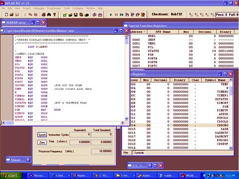
| The program as it is now ( less
the serial In from the dashPIC) is
rudderdimmer.asm. (final version) It is basically an inline program with calls to delays
and ADC routines along the way. A serial out sends data on a 2 line ( not
I2C! ) bus for rudder position and the occasional request for CDS threshold
info. It was debugged in MPASM primarily as a timing/delay checker only. This program is public domain but comes with no expressed or implied warranties blah blah blah. It was written in PIC assembly, not PICc. So if you hack with "higher" languages, you may have a bit of work to do. |
 |
| I photo etched the board with
positive resist based on a flash drawn layout. ( I like keeping it simple! )
There are no datasets for the SMD dimensions, only the DIP spacing is
standard. Such things don't bother me ;) Also, another strange thing I do is to avoid holes. I hate drilling little holes and design all of my boards in reverse to the norm. The PIC chip sits on a socket that is surface mounted just like modern SMD sockets. The other chips are brutally assaulted by way of having their pointy leads cut off to a stump, thus giving more solder area. The transistors ( 2N3904, and 3906's) are regular case with their legs half chopped to lower their profile. The "D" shaped pads are the center pin and indicate the direction they are to be mounted, flat side to front. The regulators, a 7805 and a 7808 are not the usual full size. They are SOT sized as I have found they don't draw as much current while under no load. Not a lot of research was done on that as I am the R&D, designer, programmer, and manufacturing dept.'s all at once and time is at a premium. The D/U switch must common to ground as does the CDS, which incidentally was an afterthought off pin#14 (portB,4) I obviously has intentions on putting something there because there are 3 conveniently placed pads right next to the pin. |
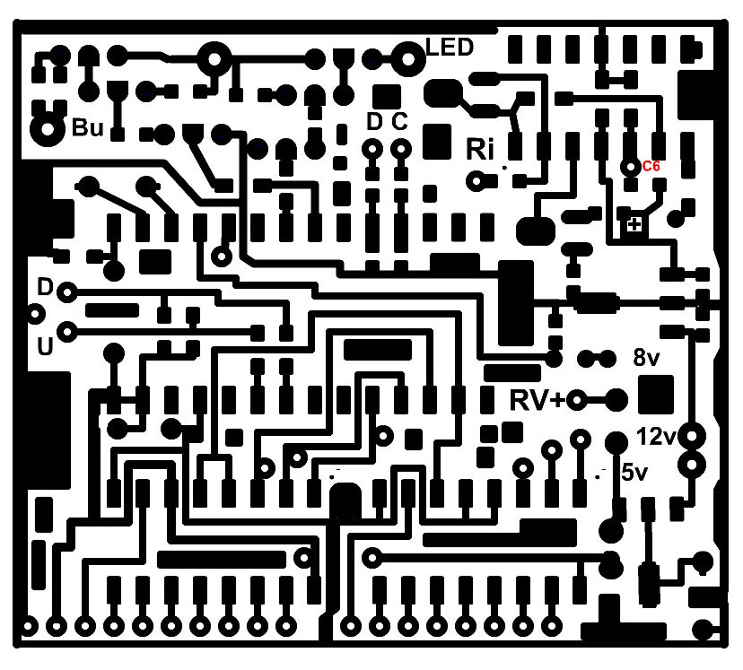 The dots just off the chip's corners denote pin1 |
LED board saves space /
board size. Resistors jumping to board are 100 ohm |
|
| The LED bar board has 2 SMD 20 ohm
resistors I added that aren't in the schematic on the anode bus. This is to
perhaps save LEDs in the event of an accidental happening on the test bench,
i.e. a chunk of solder or a tool grounding off an LED. It gives them a
fighting chance to survive! Just a safety precaution.
To view a full scale image of each board for
photo-etching, just click on the images. Right click those and Save As...
Sizing them to real life is your baby, if you decide to make this creature
for yourself. And remember not to try this until I have finished it! There may be some major problem I have overlooked. It seems to work right now, but hey, only a real test in the boat will prove it's worth. |
 This is what it will look like (hopefully!) when done |
| I originally was
going to drill 15 holes in the dash and put this behind it inside a little
plastic case ripped off from an old CoCoIII diskdrive port, but now I'm
thinking and top of the dash in a low profile routed wood case might be
cooler! Stay tuned! 11 Dec, 2007 Update Feb 2008 UPDATES pending.-photos, operation, user
opinion (Gena!) TX TO DASHPIC: -Also rudderdimmer.asm file updated to include a startup splash for self test, start and hold conditions, hold [down] button during power up to manually set CDS dayt - night mode threshold level, as well as hold [up] button during power up to auto-set CDS threshold to present light level. (Useful!!) -Hardware changes: -Filtering for EMI: An el. cap (100uf) on +12 volts to gnd, and another 100 uF at 12volt distribution to PWM Q's( between C of Q 3 and Q6 to nearby gnd trace) ..I used a nearby AM radio tuned to a weak station to verify changes. ---------more tests-------- .Feb 6th 2008.
This board had to be added to output to bulbs
as they draw over 300 mA! Ugg! If the units weren't sealed, I would change
them. The little relay is to keep engine related dash lights off unless
engine is on. A last minute update from Gena. The 220uF cap. is my revenge,
a 5 second delay hehehe! Photos of unit in place will be posted once
"developed".
|
|
to antenna switch |
Stay in touch! |
to level sensor |

