| The Big Sailboat Little PIC Project Level sensor for septic tank & New Design |
|||||||||||||||||
|---|---|---|---|---|---|---|---|---|---|---|---|---|---|---|---|---|---|
|
|||||||||||||||||
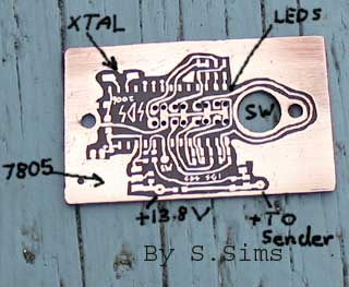
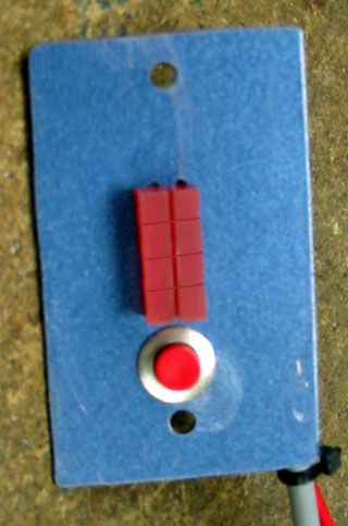
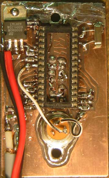
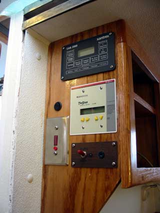
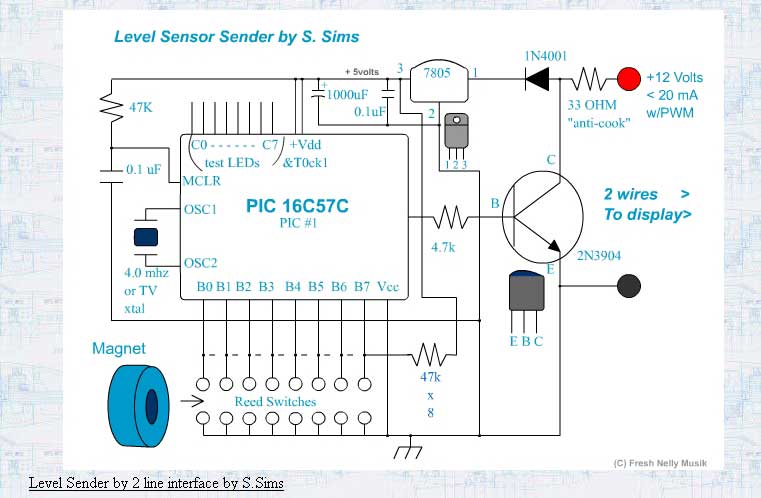
| Level Sender by 2 line interface by S.Sims <RIGHT CLICK HERE TO SAVE DIAGRAM> The level sender is a board that is mounted inside a waterproof housing at the top of a fitting on top of the septic tank. The display board, discussed below, tells the user the level of the tank via 8 LEDs and a button. The power consumption is very low as both chips are mostly is "sleep" mode. This is a mode where the chips retain their memory, but aren't actually executing any program instructions. The chips ( AKA PIC chips ) consume only micro-amps and could run for years off of a 9 volt battery. How's that for power efficient?! |
|||||||||||||||||
 |
|||||||||||||||||
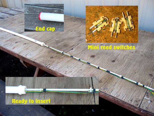
| Circuit description and theory Both the sender and display boards use 16C57C PIC chips from MicroChip. I have since graduated to larger, more impressive PIC's but these seemed appropriate for the simple function. 16C55's could also be used as the program memory doesn't go beyond the first page. In the level tube are placed 8 reed switches, each spaced about 6" apart. These reeds have a board mount attached but any type will do.(Electronic Goldmine, All electronics) The magnet, a doughnut style in this case, slides up and down the tube activating the reeds in sequence, shorting port B 0 to 7 down to ground. In their normally open state they are pulled up by 47k resistors to 5 volts. |
|||||||||||||||||
 "Doughnut" style magnet encased in packing foam then coated |
|||||||||||||||||
A simple reading of the reeds couldn't be implemented as sometimes no reeds are closed, and other times 2 may be closed at the same time. A memory of last position and direction must be kept. Because of the motion of a boat, water sloshing around in the tank may give a falsely lower reading. To remedy this, the level doesn't drop until 2 reeds in sequence have been activated. This should only occur during a pumpout. ( or knock down God forbid! ) The lowest reed invokes a reset condition only if it has gone down to that level. A beeper will sound on the display to notify user that the tank has been emptied. This could also be tied into the pump-out pump as a shutoff but I don't think we'll bother with that. The chip sends data to the display board by pulsing the transistor which pulls down the 12 volt line to ground. This 12 volt line is fed from a 470 ohm resistor on the display board. The power supply is the key to low power consumption required on a sailboat. A smaller cousin of the 7805 is used. The UA7805CDCYR (Digikey) is an smd version that has less power consumption in a no load situation. A capacitor on both input and output pins to ground stops oscillation.( Very necessary!) A 1000uF electrolytic capacitor holds voltage to the chip while the 12 volt feed is being pulsed with data to the display. The pulses are extremely fast (1 mS) and have no effect on the voltage to the chip. They are only sent when the chip "wakes up" and takes a reading to update the position of the magnet. The rectifier is to stop any current feeding back into the line from the 100uF capacitor. The 33 ohm resistor is just a precaution for accidental reverse voltage or whatever! (I have a lot of experience in this!) During testing, I connected 8 LEDs and 1k resistors to Port C outputs. These don't need to be connected so have been left out of the schematic. If you want an 8 wire indicator without the cost of the display, these can be used but the lines of code rem'ed out in the sender program must be put back in as well as the tris port C changed from 0xff to 0x00 to make port C an output. ( Outputs waste power ) A 4 mhz crystal was used ( XT config bit not HS ) but a TV colorburst crystal 3.1519... would suffice. As long as both crystals on both boards are the same. The MCLR pin has the standard reset on power-up configuration with a 47k and .1 cap. Problems: --2 reeds being active at the same time. This would lock up the original program but was remedied but counting down from the fullest toward the emptiest, taking the fullest reading ( which is more important, right? ) --serial data format. I chose a PWM format. One's are 50% longer than zero's, but each falling edge is the same clock spacing. I did this because the original idea for the display PIC was to have it wake randomly and count 9 bits. If less than 9 bits the data invalid. This turned out to be dodgy because in order to get a sync, minutes could pass. During emptying, minutes are irrelevant. Seconds are relevant. I just kept the PWM because it's one way it works well on a single line (really) communication method. --No reeds active. The display PIC must be able to remember as well! Button gets pressed to check reading, problem solved. --Data getting corrupted over long runs of wire. Because this is a non-twisted pair serial connection,(rs-232,nmea) higher data rates cause data to be corrupted by resonance of the wire. ( A common problem, I should know better!) The solution was to slow it down by 3 decimal places. How many thousand times does one really need to update a septic tank reading every second haha!
<RIGHT CLICK HERE TO SAVE DIAGRAM>
|
|||||||||||||||||
|
|||||||||||||||||
 ...
... 
