| Day 404 |
 |
Take up tank &
Pedestal |
| Every car has a radiator with built in tank. This engine needs something similar, a tank to fill the cooling system and to allow for expansion. As the water cooling system holds rather a lot of water, there must be a fair sized tank attached to it. Capacity must be about 1 quart for every 8 gallons in the system. | ||
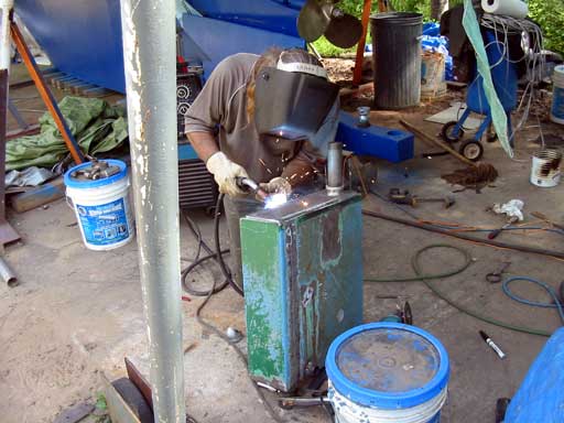
 Shortened tank, welding a top on |
I always like to make a clean
start and just build something, but Gena likes to modify things to suit.
She found this tank a while back at the scrap yard. It was oversize so
needed to be cut down. The photo left shows the lid being welded on along with a fitting attached. It's been a while since Gena has done any welding, and I was a little paranoid I was going to catch hell about the condition of the welder after I have used it so much without maintaining this and that. Either she forgot, didn't care, or just couldn't find me lol! |
|
| The main attribute of the tank, besides the size, is that it be sealed completely to 20 psi or so. | ||
 Perfect fit!! Inside tacked.  |
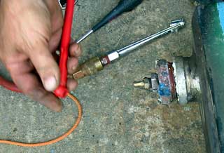
The valve Gena adapted to the
fitting on the tank ( it amazes me when she does this kind of thing! )
is used to fill the tank with air. A compression plug was used to seal
the large pipe on the face, which shot out once at 1000 kph! Just like
an air rifle.
|
|||||
As shown in the diagram,
a bypass valve has been included. This idea was implemented by someone
on the Metal Boat Society forum, and makes sense. With so much cooling
ability in the hull, it's almost necessary to put in a valve that will
allow a certain amount of water back into the engine. Once set, it
should be able to be left alone. There are temperature sensors on the
return and hot side so it can be monitored from the dash.
|
||||||
| My project was a bit less involved ( and less dangerous! ) and has been anticipated for a long time. The pedestal/binnacle is finally under way! The head that will hold the bearings/ shaft/ and chain sprocket, has been a continuing issue. | |
| As shown in the
Gallery photo, the head was originally going to be quite a bit larger
but due to the height of the compass and the display above it, the head had
to be shrunk down to a bare minimum. This ruled out the possibility of
"rolling" the thin stainless plate reserved for the purpose without a
machine shop/fabricator. The shaft is the same as what was used in the pilot house, 1". This is a very common size so the bearing blocks are cheap and available. We were fully ready to use one of our quality stainless cooking pots as for the enclosure when I spotted a cool looking heavily made
pot in Canadian Tire. I think it is for ice, but could be used for anything as it has no handle. The gauge seems heavy enough so I bought it! |
 |
| A hole was carefully plasma cut
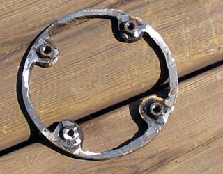
out so as not to damage the nice shiny finish. Next a ring to mount the aft bearing on was cut out. This will support the bearing and will be connected to the support pipe for strength. Because the ring is hidden there's no point in prettying it up. (This close to launch an air of impatience is emerging! ) Nuts were carefully welded on to the ring which will allow access to the sprocket and forward bearing. The photo below shows everything together. The corners of the bearings had to be ground off a bit to fit. Boy am I lucky to have found that "pot"! Next
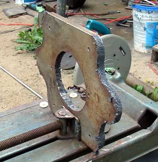
the base, and odd looking thing, was cut out from 1/2" plate. The little
ears are for the handrail mounts. |
  |
 |
 |
| After a visual check up the pipe,
the pot was welded on very carefully. Short welds and long cooling time made
sure the thing didn't loose it's shape.
This will be my project again tomorrow by the looks of it, but then Rome wasn't built in a day right? |
 |
Day 404:
9 hours: Put together tank for cooling engine system, Started the pedistal.