Project 1 Building the hull frames

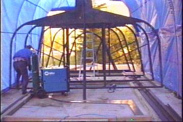
Spring of '99 came around and we were finally ready to start preparations for building our boat. In May the weather began to co-operate, so we put in a 50' concrete pad with holes every 3' to mount pipes in for our make-shift tarp shed.
We also built a small steel shed to put all the 'big' tools in. In June we built the tent out of triple sections of 10' fence pipe and pulled over a tarp. It is now 36' long.
Then we built a gantry out of old drill stem, which proved to be very difficult to cut before we had the plasma cutter, in the shape of two A-frames with a 6" bar connecting the two.
Of course the tent would have to be removed to use it as it is 16' high by 16' wide.
Instead of using a couple of old railroad tracks, we decided to use heavy rubber wheels to move it back and forth.

In early July we purchased the plasma cutter, which I must say, is an amazing piece of equipment. It can slice through 1/4" plate at almost and inch a second! Much easier than conventional means. We have yet to purchase a large Mig welder but our small one will do for tacking pieces together.

Sorry no pic, you haven't .jpg recognitionThe 
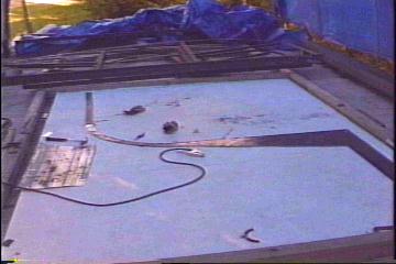
steel arrived last week and we are ready to draw on the patterns from the blue-prints so I consider this day 1. In the photo is our first plate drawn out.
Day 1:
8 hours. Moved plate into position, cut up and taped plans, then traced onto first two 5'x10' plates. This is for the webbing. The weather became rainy and the air humid. Blue-prints don't like humidity so there were several times we couldn't do anything but wait.


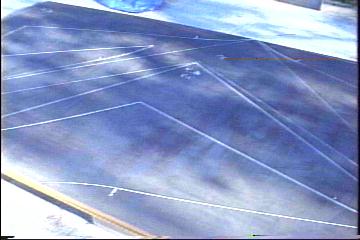
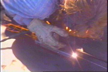
Cut up 12 pieces of webbing
using the plasma cutter,
Genas home-made travel car,
and my freehand abilities.
(lucky me!!)
The first 2 webbing halves cut!
After 9 hours (less lunch) we
finished the first 12 pieces
That makes 6 webs (frames)


Cut ten more pieces for webbing from sheets
3 & 4. Free-handed curved sections close for
minimum grinding time. Only 8 hours including
copying blueprints to steel, we're getting better!
(Shown at right: paper cut-outs on a proportional paper, 1x2)
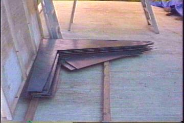
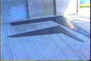
22 cut pieces ready for grinding. The stack is only 6" high but weighs over 1500 lbs!

The biggest problem we had working with this plate was the fact that it was not cut square! So there was a lot of trimming involved, which used up a lot of time. As amateur carpenters, we only assumed they would be square. ( ASSUME=ASS out of U and ME! ) In the future, we'll make it a point.

We're no experts when it comes to plasma cutting,
but here's a few things we learned using one:
-Always brace you arms) for stability. It's amazing how quickly it cuts errors!
-Don't use a plasma cutter to 'trim' thin sheaves of steel off edge, unless
you like replacing tips after every cut!
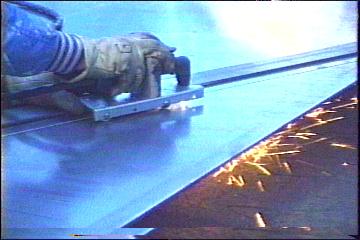
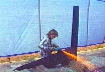
-If you need to cut a straight edge, do like we did. Make a little cart
to mount the gun on, with wheels. You can see it in some of the
photos. It remains at a constant height, and along a straight flat bar, perfect!
-Work up to a constant speed just below where it can't penetrate fast enough
to cut right through. (Use a practice piece of plate for this! ) This way the
steel can't blob up and it makes for a very clean cut, and less grinding.
-Free handing, even with the cart, is difficult. You have to look at the beam
and near it to see where you're going. I used a #5 shade and don't recommend it.
The marked line is easier to see but I had to move my eyes around constantly to
prevent a nasty case of 'flash' later on! ( Flash is a 'sand in your eye' feeling that
welders frequently get, that lasts for hours. Not pleasant!) Try #6 or #7 filters first.
-If you have no hand-eye co-ordination at all, I would recommend building a
motorized jig to attach to the cart via a piece of greased 'ready-rod', with a variable
speed control.( Look in hobby shops) All you would have to do is hold the trigger
for the cutter down with one hand and the motor control with the other. We're
thinking about doing this for cutting the large hull plating.

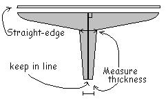
Day  4 was actually several days during the week spent during slow times at work grinding and comparing sizes. It has became apparent that accurate cuts are very important as grinding is very time consuming and labor intensive!
Also setting out the blue prints in only dry weather conditions is a must. We noticed that laying the warm plans on a cool plywood table made a difference, probably due to a bit of moisture present on the plywood. Firstly we lay the cut piece over the plans and plastic to check the lines. Then we grind off any extra on the curved sections. Test the piece at the sole line for straightness, and finally grind down the center side to make even while measuring thickness at known points.(ie tip of keel and top of keel)


Put in the earplugs and ground webs all day long! Started to rain in the late afternoon and blueprints started to grow in size so had to stop. Also arranged plating numerically to put some order to chaos!
Another fun day of cutting with the plasma cutter! This time it was hard to make a mistake though as we have rigged a radius guide comprised of Gena's amazing guide car, a ruler, a large CB antenna magnet-mount, and some precision measuring. See day 6-10 for photo. The radius came out exactly right! (Give or take 1/32").
Unfortunately we found that some of the radii were to be slightly greater, and some less. Should be easy enough to bend them out or in by 1/8".

Gena grinding off slag
During the week we also have been grinding the webs every chance we got, but figure there is a few more hours to do there. Estimate 12 hours of grinding over the past week.


The more the merrier seems to be the rule with support for the frames! We cut lots of flat bar for the frames and exact lengths of headstock. That's what goes across the strong back that will eventually hold up the whole boat while upside down. The lengths are important as this determines the width of each section of frame.  
We also laid out the plans onto 3/8" white painted plywood and drew out 1/2 of the frames (the right side of the full sized plans) with the aid of a thumbtack and a water fast pen. Then we checked out some of the radius pieces against the lines and found some indeed would have to be slightly bent one way or the other to match up.


We decided to make the strong back out of 4x4 treated lumber as it is less expensive than doubled 2x6 and is available. Putting it together was the easy part! Getting it all perfectly level was another story!  
Using a time tested method we obtained reasonable accuracy (we think!) as the 4' level couldn't find an error. Fill a transparent hose with water and decide on a height above the highest point of the frame, then lowering or raising the other end also on a ruler, until the high end was at the decided level. This would then tell us how far the other end point was out. We then raised the beam with metal shims.
( Finally found a use for all that stainless steel flat bar we had laying around that we never used! ) This was done at various points around the frame. The true size of our sailboat to be has become apparent at this point. We could have made the work area a 'bit' larger!


Getting down to business!
It seems like a simple task: lay down the pieces match them up to the lines on the plans, cut off accordingly and put together. But little things like a warp in the (cheap) 3/8" ply can play havoc with the flow of things getting done. Lesson learned: use only the finest materials, they may be more expensive, but they're worth their weight in gold time-wise, and become a burden if not.
Welding is a bit like making a card-castle with silly putty. After the silly putty is applied between two cards to hold them together, and you release your finger from pressing it on, the putty tends to retract towards a more rounded shape. This action will pull the cards closer together and change their origional intended position.
In welding, this motion can be countered to an extent by tacking first, then welding the other side in the same area as first weld...after cooling.....
We haven't quite got it down-pat yet, so out came the 20 lb sledge!
 
Despite all the problems with the ply, everything worked out and eventually lined up to the plans. Each joint was ground in at 30 degrees before welding, then tacked to reduce deforming. With practice it became better and moved less during cooling.


Today we welded together the web and frame halves for stations 0, 1, 2, 3, & 4. We lifted each up and plumbed them to be sure they were centered and even left to right, then welded them to the headstock angle pieces. Then put in some bracing from the web to the headstock, and smaller braces out to just below the radius join. Surprisingly they were all pretty close to plumb center right off.  
It was then while lifting station 4 into place that we noticed that our tent wouldn't be high enough for stations 5, 6 ,7 & 8! A miscalculation on my part, forgetting to add in the height of the strong back! We'll have to raise it some before putting up the frames.
Put together some of the half station webs. These are the ones that have no frames, just the web. Also beveled frame 8 for next weekend.  
Copied 2nd half of plans to plywood after paint had dried. The weather slowed that down. Had to wait for things to dry up as it had rained the night before. It's amazing how much the plans will grow in high humidity. One must be very careful to keep them dry, and watch humidity while using the plans.

Some of the frames are comprised of 4 separate sections per side, the web to sole line, the straight section to continue the web past the sole line, the radius section, and the straight section leading to and above the sheer line. This kept us busy for the first 3 1/2 hours of day 12.
Welded together web 7.5 at the same time.

Gena welding 7.5

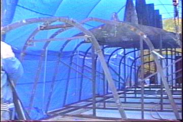
Completed and plumbed frames 8, 9, & 10. Finished half of frame 7. They are all pretty light so lifted them by hand. Will likely find it necessary to lift frames 5, 6 & 7 with the hoist. ( Finally we may get to use it this year! ) Next weekend we plan on actually erecting some of the frames! Luckily the weather is holding out.


Frames 3 - 6 in place: Sure is bigger than we expected!


At last we have begun to erect some frames! After completing frames 5 & 6, we decided to use the hoist for the first time and put them up, along with frames 4 & 3. After placing some short 3' 2x2 angle irons as spacers the frames became fairly rigid, but we put in some diagonals just to be on the safe side.
We also have raised the tent by 2 feet and have nearly a foot of clearance above the keel height for accessibility. (1.5 hours) Not much room in the tent for moving around though. The strong back needed some leveling after being moved around by dropping plate onto and pulling the welder over it. (1 hour)

Frame # 5 up but not perfect.
After the frames were put up, we noticed that frame 5 was too high by 1/2" and we're not sure why, as we'd just had it on the plans. We'll have to grind off the supports and see if it will come down again.

Making some measurements off of the plans can be useful for checking heights and widths in the assembled frames to assure accuracy. We're going to do that for the next frames to take away some paranoia! Frame 7 left to complete, hopefully during the week in the evening sometime. Then the rest can be put up at leisure. We couldn't ask for better weather !! ;o))

Whenever one takes on a project of this magnitude, particularly if the project is to be done outside, at the will and whim of the weather, we find ourselves to be pressed by time. In our hurry to erect the frames we have encountered a few errors in the sole height, especially in the fore-mentioned frame 5. Other errors are bound to creep in as we continue to race against the inevitable onrush of winter in all it's icy, snow filled glory! In this part of the world, autumn has a bad habit of suddenly becoming winter, long before the calendar says it should be winter.
Welding the stem
to frame number 0


We completed frame 7 and put it up, then frame 8 and frame 9. Much of the day was used up bending the stem bar to the patterns. This is a rather important part of the boat as it becomes the leading edge of the bow, the edge the plate butts up to a fine ( hopefully fair ) sharp edge.
After much time and even some frustration we managed to get it just right. ( That means close as our patience would allow! )
  To relax from bending the stem, we put up frames 0, 1 and 2. Braced frame 1 and 2 then cut out slots for stem bar. After welding the stem bar in place, we realized that the highest part of the stem piece should have had a slight curve...
There's one of those unforeseen problems I mentioned! We plan on cutting off the extra piece on the stem just after
 
frame 1 ( you can see it in picture above ), then putting a slight bend into the remaining piece of stem that goes to frame 2 and 3, and pulling it the rest of the way into position.
That pretty much did it for day 14.


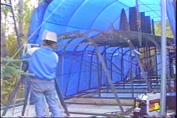
Frames 0, 1 & 2 up and fitting stem (part of stem) in place

Today was the day to fix mistakes and check out the fairness of the frames both horizontally and vertically. We fixed the problem with frame 5 by releasing the supports and dropping it down to the proper height with respect to the others. Unfortunately, we noticed that after doing this, all the frames were out forward and back. This was because the main diagonal supports were from frme 5 to frame 4. Dropping frame 5 released the pressure on it's headstock, which rose up and

Stem continues to frame 3
pushed on the diagonals, which in turn shifted the frames all out of plumb. After we corrected that problem by repositioning the diagonals to straighten the fore-frames, frame 5's head stock bent out of position and stressed all the aft frames back further than they should have been! So we released the stress on the diagonals once more, and tied all the headstock (base)
pieces together with some 1" angle iron. Finally everything was correct again.
Next, we continued the stem bar up to and through frame three. ( Above photo ) The bar had to have such a small curve to it we were sure it wouldn't be fair. As it turns out, we got it right the first try! You can see how fair the upper part of the


stem is from this photo, as it passes over the 2nd frame onto the third etc.
To finish off we put in some supports out to the radii on frames 7 & 8, then put up the last frame, number 10. The weather was relatively cooperative as it rained only for a few minutes, but the temperature was only up to 10 degrees C.
 
We are confident that all of the stations are true enough to start putting on the stringers, the horizontal framing that runs the full length of the boat.


to Individual projects main page

Forum <- - -> Boatcam