
| Project 40 |  |
Experimental Engine Cooling System |
| The conventional
method of cooling an engine in a marine environment is to have a seacock
where salt water can be drawn in and used to cool an internal water
circuit connected to the engine. These units require diligent maintenance,
especially with sacrificial anodes, or they will corrode very quickly. There is another alternative with steel boats that makes more sense to us, closed loop keel cooling. |
|||
 |
|
||
 |
|
||
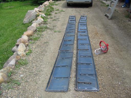
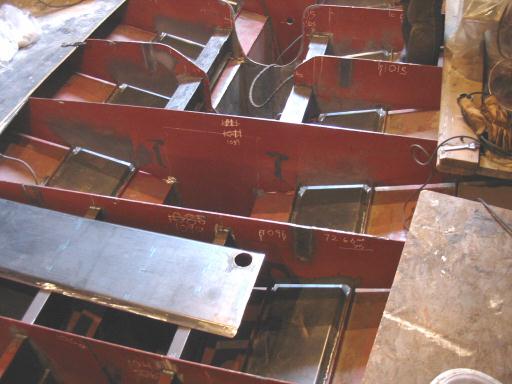
| The photo right shows how the
cooling units will go together once against the hull. The 1" flatbar is just tacked in as we saw no real reason to weld them in solid. The ends are tacked in now so they will be easy to weld on once in place. We could have just added a piece of flatbar on after, but this way 2 sides can be welded. Why tempt fate? Before installation, the insides will be brushed clean of any loose slag. ( Not something you want flowing through the engines water pump! ) |
 |
||
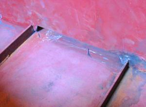 |
To the right is one of
the slots cut out under the web frames. Note that the stringers are not
compromised and all of the plate will fit between the stringers in place
with enough each side to weld. The hull plate will be sandblasted ( yuk! ) then the pieces, each four feet in length, will be slid in from aft, where there are frames nearly 4 feet apart. This all works out very well being able to slide longer pieces in, thus less welding. Placing the holes for circulation was a subject of some debate. We are confident the approx. 32 square feet of area will give ample cooling, and hope to have to use the bypass valve to an extent! Guess we won't know for sure until she is in the water, with the engine running. |
||
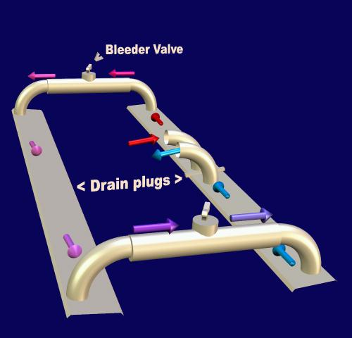
| To the left is a little ( cool
3d! ) diagram of the circulation. The take-up or expansion tank will go on
the hot side, and a bypass valve.
The diagram shows how the circulation will
work. The holes at the ends are also the high points ( except the fill
tank ) and the pipe connecting them must have bleeder valves to get
trapped air out apon filling. |
 |
||
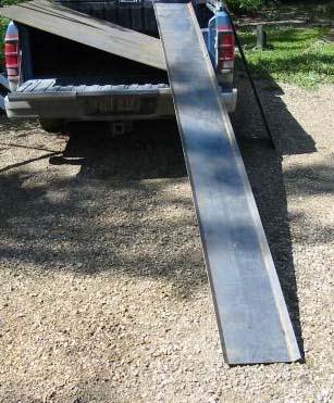
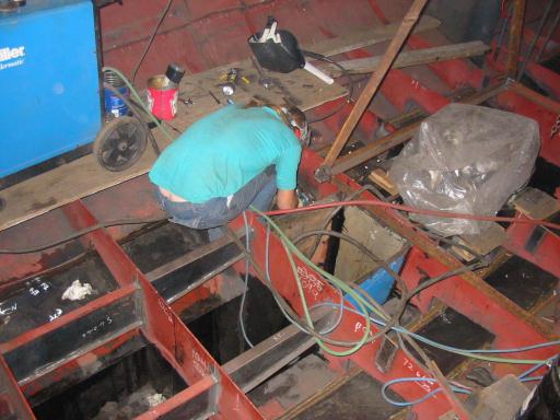
| Here's the sections going into
place. They had to be slid back from the forward frames which aren't full
webs so there's more room. It's a good thing Gena was reading through an article in "Metal Boat Society" magazine (recommended! ) that happened to mention drains in thru-hull cooling. We'd never have thought of it!
|
|
||
| Gena is still
taking a good amount of time to work on the hull cooling tanks, and making
progress! She has patience I couldn't even come close to. 1 hour at that and I'm ready to hit the bottle! |
|||
| Many days have passed and
still the hull cooling isn't finished. I was ordered ( rather than
asked ) to cut the holes in the webs bigger. I expressed concern about
weakening the structure but was re-assured the pieces would be welded back
in afterwards. Needless to say, Gena is getting pretty frustrated with the whole thing. If we'd have made them 2" narrower, getting a good weld would be much easier. The problem is, the stringers are in the way, running alongside. Even though the box is a 45º angle, the welds can't be done well. When pressure tested to 10 psi, the leaks are always under the webs, so the angle of the welding torch there is an issue. |
 |
||
 |
A month more of weekends later.... At long last the hull cooling units are in and no leaks. Gena has been using the time-tested soapy water method for testing for air leaks. No more bubbles! Bravo Gena. The performance after running the engine one land for an hour, looks promising. Even in air, only 1/4 of the hull area was hot, 1/4 warm, and the other half not noticeably warmer than the rest of the hull. During sea trials, (shakedown) running up to 4 hours under load, the bypass valve, that is, a valve that controls how much water loops past the cooling system, had to be opened some as there was much too much cooling. The gauge never got above 170º F! In my (inexperienced) opinion, less than half of this system would easily cool any 60 horsepower diesel engine. Now that we know it works, we can't imagine why anyone with a metal boat would want to use the "old" method of transferring heat to salt water in an exchanger. Just the "forget anode/destroy engine" issue was enough to turn us off it. |
![]()
to Individual projects main page