| Project 6 |  |
Hull plating |
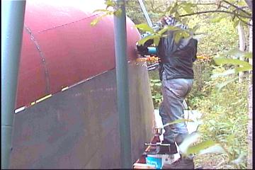
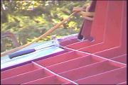
| Wow!!! We
actually managed such a large piece of plate with our little hoist, some
clamps, grinding teeth, and a badly sprained ankle! (Mine) The piece of plate is 24 feet long, so handled like a wet noodle, much more flexible than we thought...and heavy. It wasn't so much a matter of lifting it into place as it was trying to stop the ends from flopping back and forth. First it was moved into place and jacked up to a suitable height. ( Pic above ) The old plate clamp we had acquired did its job in its strange way of gripping hard on the plate using the downward force of the plate pulling on the teeth. Although I still think my teeth were clamped together even harder! I just can't trust something that can hold that kind of weight, without leaving so much as a scratch or nick... anyway... The Bottom would be left oversize below the sheer-line so we will have the option of fairing whatever type of bulwarks we decide upon in the future. Instead of pulling it in, making a mark, letting it down, then cutting, we decided to just cut along using the radius plates edge as a guide. Using a torch this way probably wouldn't work, and the designer recommended against it as it would result in an unfair hull. With a Pasma cutter on the other hand it's not a problem! There was a bit of a mess created at one point where the radius plate somehow grew a bulge over the last while. We of course didn't notice as we were eager to work with the plate, and it resulted in some ( I'd rather not mention it! ) more desperate measures! As you can see in the pics below, all came out well in the end! |
||
 Plate cut using bottom of radius plate as template |
 Grinding the edges for good fit all along join |
 Plate tacked into place at top but left hanging |
| Tomorrow we will check the other
side for any problems before we start with the plate. I'm still
amazed we could get away with serving up such a long piece. This was done
to reduce the vertical welds that would be visible above the water line.
It really looks good! As for my sprained ankle: I should have been wearing my workboots! |
||
The other aft side plate was much
easier, being our second experience with large plate. It was somewhat difficult
to maneuver over and around the aft of the hull into position, but was much
easier to bring into alignment. As can be seen in the pic above, the 3/8" gap
left by the plasma cutter is just enough room to allow the grinder to do it's
job. ( With the help of Gena of course! )
It seems that letting the stringers out to the plate in this case will be the
correct thing to do as pulling it in would definitely make it unfair. The
importance of completely ironing out any coning or non fairness in the radius
pieces becomes very obvious once installing the sides begins. They must not only
curve down to the predesignated beginning of the straight section of the frame,
but also be exactly parallel to the direction the frame is pointing down to. If
not, a "humped bulge" look would occur. When I look at it, I imagine there is
one, but after checking it with a straight edge I'm reassured there isn't.
Surprisingly, the plate tends to have a slight curve looking downwards. Once all
the sides are done, we will decide whether or not to let it go that way.
| Today we put up the largest of
all of the pieces of plate. 23' x 5'. There was some difficulty getting the plate aligned as it was just big enough height-wise to reach 1" below the sheer-line up to the radius plate. In the pic above you can see that we had to push it in near the center to facilitate a close fit for cutting. |
||
 Cutting along radius plate |
 Grinding even for butting |
 Grinding bow edge |
| The methods we learned yesterday
worked just fine again today. Each time gets easier as we know what to
look for and how to avoid problems with butting evenly. Keeping the plate in tight before cutting assures an accurate cut Don't force plate in too tight and always look ahead for the possibility that it may bind together too tight as welds shrink. Make sure the plate that you're butting against is fair in the first place. |
||
 |
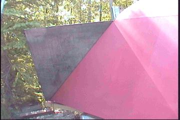
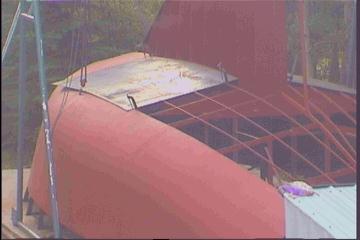
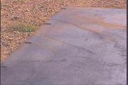
If there was a bad area in this part of the
hull, the "wet primer test" ( I made that up! ) would surely show it. I have other photos of wet paint but due to loading time on the net I'll have to hold off on that one! Just a preview of the finished hull...it's very inspiring. |
|
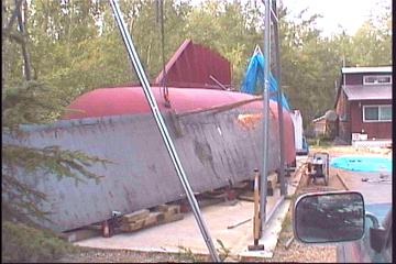
| At last the hull looks like a solid entity. Of course many curious neighbors came by and expressed their congrats. I guess it's hard not to notice as one is driving by. This was a long weekend and we feel as though we accomplished a lot in three days. Didn't relax or go swimming or sailing at all, in lieu of planning the "big" holiday! | ||

Actually looks like a boat!
| The other largest plate had to
be hoisted up and over the front of the boat to get it into position. A
slight kink resulted in the 23' long piece as it flopped right over 90
degrees or more. This was worked out using the frame straightener made
last year. Guess we should have braced it with some angle stock like we
did before... Anyway, all went in as planned. The bow cutoff was probably the hardest to do. We are going to add in a 1/4" steel rod on each side as the welding there may be a bit too much to fill, and the rod will act as a filler. |
 |
Next came a whole new experience.
The bottom plate. Upon deciding to start at the bow end, a 13' x 4' plate
was split diagonally to accommodate both sides, thus cutting back on waste.
Templates were considered but the pieces aren't too big so we opted that out
for this weekend. Working with the plate horizontally poses several challenges. The plate that is being worked on is now under our feet, for the most part. |
| Any marking for cutting must be done with the height of the plate in consideration. Mainly because it isn't perfectly horizontal. An upward movement of 1/2" can make a difference of almost 1/4" on the horizontal. Care must be taken when measuring, etc. We almost goofed on a measurement which would have ruined the whole piece. | |
 |
Even though the piece weighs a
mere 180 lbs, we had to use the hoist anyway as it was too high to push up
into position by hand. The piece has been cut and ground and is ready to go up. The weather prevented us from finishing the job today. The cut along the keel butts right up to the frame so the keel plate can sit over it, to be welded on. Also I partially cut out circles in the frames where the bottom and keel plates will meet. |
| This is to facilitate welding
constantly past the frame from the inside. The rest of the circle will be
cut out after the bottom plate has been fit. I'm sure we'll use templates for the larger pieces. I guess we'll see how this goes tomorrow! |
|
| The marked pieces were taken down for cutting and grinding. Amazingly, once put back up into place they fit quite well. We found that the notorious radius plate, just after the first join, had bulged out some. |
 Holes cut for welding pass |
Once corrected with the jack,
and some grinding to take out the overlap, it came in ok. I cut out the rest of the circles (for access to keel hull join) as the points were no longer needed. Going around the stem pipe join with a batten was the hardest to measure. |
| It is going down at a very acute
angle under the plate, and furthermore is round. I had to estimate where it
would be under the plate. Of course Gena had to grind out more than I had
cut. As you can see in the pic to the right, one plate is longer the the other. The one to the left was moved up so it wouldn't run to close to the edge as the one on the right almost did.
|
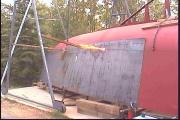
 View from high up - Both plates in |
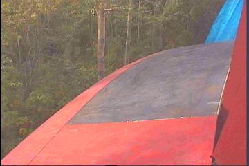
| Putting on the top plate is easy as long as the previous work done on the radius sections resulted in an even and smooth curve vertically. Today's plate was a perfect example of how accurately a piece can be cut and fit. | ||
 Slots cut out from frames of keel |
Firstly, the plate is placed
into position for maximum coverage. This wasn't a worry for this piece as
it had about 4 inches to spare. Then the maximum amount of movement toward
the center is measured, in this case 2.5", for how far it will need to
come in towards the keel. Slots are then cut out so plate can be moved inward into position. The existing radius plate and recently placed bottom plate will now act as a stencil to mark for cutting. |
|
| The plate is now removed and cut using pieces of long flatbar clamped on as a guide, always keeping the traced line on. ( As it was when being drawn ) | ||
 Perfect fit!! Inside tacked. |
The plate is then ground off to smooth the
edges, and the inside side cleaned of mill scale etc for proper priming,
then hoisted back up into position. This piece of plate laid in so
perfect, we hardly had to do any lifting or pushing to tack it into place! The forward-back evenness is important, but the way the radius rolls off from the flat plate is just as important. |
|
| We were watching it as we put on the radius plate, but only as a desire to make an even cut along the top radius stringer +1.5 inches. It's a good thing we didn't leave them straight! It would have made a huge difference to the way the bottom plate faired in to it. | ||
 |
|
||||||

| Even though the aft plates are the largest
of the bottom plates, things went in quite well. |
| As the weather turned against us,
we had to remove the pieces by hand under the tent, which was a bit scarey!
It's amazing what can be done with some determination! Before a line could
be drawn for the radius plate curve, the part of plate that sat over the aft
stem bar had to be trimmed away until a fit could be accomplished.
A straight edge couldn't be used as the
stem on the plates plane came up as a curve. Slowly trimming estimated lines
was necessary. |
 Gena grinding the aft plate to aft stem join
|
![]()
to Individual projects main page