
| Project 9 |  |
The Transom |
| The transom was cut from a frame that was made from the full sized blue prints. I had made the frame by mistake thinking it would be used at the ends of the stringers, but because the transom top is a separate entity, we never used it. |
| The transom of the boat has been a
long debated subject between us, whether to have a swim platform, solid or
stainless steel bars/steps, or inverted around the edges. We finally decided
to go with a "scoop" type of inverted transom. Of course this means more
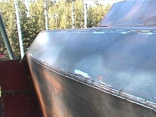
plate to be added on aft. This took some real eyeing up on my part, and patience with me on Genas (haha!) The flat part of the plate was a simple matter of lining up and tacking on, but the radius extension was compound and had to be just perfect to be fair to the rest of the hull. |
 |
| Any mistakes on these
would be VERY noticeable! Amazingly enough my estimations worked out exactly
as anticipated and the day ended on a happy note. All of the plate won't be used as the edges will curve forward as height increases. The transom plate itself will remain in almost the original intended position, only with a slight less angle towards vertical. This can be continued once the boat is turned over. |
|
| After reading many books on steel
building, we found the least covered subject was how to make the transom
fit! At first we were thinking of doing the same thing for this as we did to
put in the bulkhead aft of the pilot house. (
Using wood sticks glued to a 2x2 ) But
after some looking at it, we realised this wouldn't work ! We had no way of
knowing where the wood tips should butt into the sides and bottom. To make things even more unknown, the transom is curved in at the sides ! Here's what we did: |
 |
| -First, I
used the aft curve (on the deck) we have just cut to make another piece of
plate
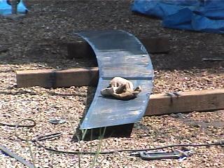
|
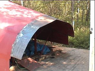
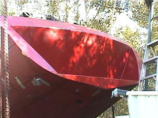
 The bizarre curve that resulted ^ after we took out the transom! 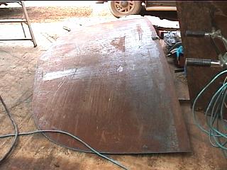 Transom ^ waiting to go in |
| Excuse the messy
primer job on the inside of the transom, above, somehow it became a place to
clean off the rollers for a while! We're finally ready to put it in for
good. For the last few months we have been cursing our leaking, melted and
holed poor old tarp and the water we have to repeatedly vacuum out of the
keel. After hauling up the engine, there's nothing to do but seal up the aft
of the boat. |
|

|
We had already cut and trimmed it
so it didn't take much to get it in. It's truly amazing how solid a curved
structure is, especially once securly in place. Shortly thereafter the
camber cut was made to the transoms' top to match the deck camber. I think
this is important so the plate that will go up at a 45º lay in will only
need have a single curve. I have seen some that are straight but they don't
seem, at least to us, very continuous looking.
The way we did this assured an equal distance
all along the angled plate, even though there is a curve in the transom. I
took an extra piece of frame that was cambered for the poop deck but never
used. Placing it in the appropriate position inside the transom and keeping
it vertical as are the ones in the poop deck, I used it as a guide to cut
the camber. |
 |
In the thick of thought
and planning, I figured that the plate between the transom and the poop deck
would be more or less straight, give or take a bit for the camber. Pic to
left says this isn't so he he. |
 |
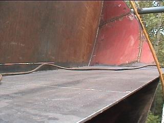
(Photo below-left) Transom Top Plate into poop deck edge. The edge is joined by a narrow section of split 3/4" pipe, as is the top edge, for a rounded look. |
 |
The addition of the 3/4" slit pipe
sections made it even more fun. Happily, everything went into place just
fine. The 45º on the cockpit coaming matches the slope off to the transom. The rest of the day was spent welding this new addition ( 42 feet - Gena must hate my split pipe sometimes ), and rejoicing in a sealed aft ! |
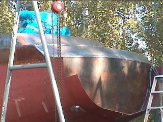
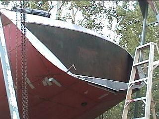
| The Sugar Scoop - Swim Deck Modification | |||
| Cutting the shape for
around the swim platform was difficult, at least the idea of it was. How could one take a shape like that and sheer off a nice line? Originally I had planned to just run a piece of flat bar around to the bottom on each side, coming off at a slightly more vertical angle than the plate coming into the transom. But then it became evident that this would cut off a lot of the swim platform. The solution was to force the flat bar into a twist as it left the center by pushing out on the bar as it passed the radius. It wasn't hard at all just tapping it out with a hammer while securely clamped at the top.
The edge near the top needed to curve into the 45º
plate so instead of trying to force that in, I just left it and rounded it
by eye afterwards. The reason I didn't want to run it in hard there is
because the rest of the cut is a curve, so to retain continuity the top
should be too. |
 |
||
 |
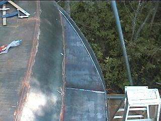
The next thing to do
is put the swim platform in. Because of the 'V' in the aft area, the platform will have to sit about 8" above the center to get any reasonable width. Flat things seem to have no place on the hull of a boat but this was almost unavoidable! First the transoms curve had to be derived. This was easy as we still have the piece that was used to curve the transom. Next the sides point inward as they move aft. As the width of the platform was to be 6 feet, and the curve length is to be 100.5" , the length between the transom and the edge of the platform where it meets the hull on each side should be enough dimensions to draw it up. I took a perpendicular tangent measurement off the transom to the point where it meets the hull and the measurements came true! |
||
 |
 |
||
| These lines also have
a curve which had to be just roughed in for now. In the photo to right the
tips appear to be nipped off but that's just because we didn't have any
plate longer than 8 feet. When we put it in place it was quite drastically oversize, so trimming and grinding can bring it in closer. Something we hadn't considered was that the platform should have a slight tilt downward to prevent water being trapped in the corners. Oversize is a good thing! |
|||
 |
Using some what was
almost was scrap, 1/8" thick 12" wide strips of plate, we marked cut and
bent into place the aft vertical edge of the swim deck. They went in with
some resistance as they also had to twist outwards near the bottom. Getting
the curve cut right took a couple of tries on the first one. It was necessary that they be inset into the hull plate rather than sitting on top, so a soft edge could be ground away later. Better it be ground off the thick plate! |
 |
|
 |
It took a while to
decide how the sides should come in to the bottom, and obtaining the max
width on the swim deck is priority. I origionally wanted the sides to come
down equally with the hull shape, but even a 4" thickness there would have
substantially chewed space off the deck width. We have left some curve in the sides to minimize need for support framing. The bottom plate was cut to fit into the hull plate just as were the sides. It was pretty easy to do considering the whole piece actually twists as it approaches the center. All that worry for nothing! |
||
| In the photo above ^^, you can see
the solution for smoothing off the join. As all the aft edges are going to
be left fairly "sharp", using a piece of split pipe here probably would have
looked out of place. Some "humanization" is required though as I imagine
we'll be sitting on this for diving preparation, boarding the dingy etc. 3/8" steel rod will make a nice prompt rounded edge. The plate can't be welded in yet as Gena painted the inside and it needs the dry! Once this is on we will no longer have access to the area inside. It is a huge open space, and although it's tempting to use for a storage area, we won't. Cutting a big hole from inside would weaken the structure ( we think ) and after having read about the constant problem of external lockers leaking and filling with water, we definitely won't be accessing it from the outside. |
|
| Gena has been welding the ( more
or less ) triangle shaped side pieces I cut earlier. This pieces were traced
off of the edge and took both of us to get it bent into position for
marking. The corner is actually 90º still. We just moved it back until it
fit flush against the transom ! As the edge is inset instead of on top, care
was given to the accuracy of the cut - well it usually is, but even more
here! Below is the final result with all the ornaments ( handrails, steps, ladder, little port lights, etc.. ) in place. Having this "lower deck" is very convenient and I couldn't imagine not having it. The weight aft is a bit high, and anyone doing this might want to consider using 1/8" plate instead. |
 |
 |
 |
![]()
![]()
to Individual projects main page
