| Boat Stereo |  |
Great audio with small power |
| Boat Stereo | |
Great audio with small power |
| As mentioned before on the site, standard "car" stereo systems can be a real power draw even when off. After looking around and checking many stereos that come into the shop for repair, I have come to the conclusion that there is no such thing as a low draw in-dash radio. | Shown above: cell phone box transformed |
| The amps when not active still manage to guzzle current, and the display can be quite a hog. Especially on the newer units. I guess they just don't have saving power in mind as much as how many lights and doo-dads and raw watts of power there is. | |
 |
We considered using a
portable ghetto-blaster type of unit, but the shape of those is all
wrong...round!
The only solution is to just make one.
Really it's simple enough, and that way we get what we want. There must be 5 input selections to the amps. One from the TV, one from the DVD ( for listening to CDs etc ), one from the little shortwave radio, one from my studio ( just because it'd be cool!), and an external input on the face panel for mp3 player etc. Because of the ultra low price of Flash micro controllers these days, I am forgoing the old switching method of a rotary or ttl counter chips. A pushbutton selector with LEDs will be small and cool! Each time the button is pressed, a different LED indicates the next input in the sequence. How the audio lines will be switched is still in the "deciding" process. Latching relays may be the way to go if I can sneak around my Scottish side a bit ( They're a bit pricey ) and buy some more. They have 2 coils, Once actuated, they don't require power! Pretty cool little things. CMOS analogue switches are what I have used for this sort of thing in the past, but are very static sensitive and during a lightning storm with the long speaker wires projecting outward like Tesla antennae.. need I say more. |
| 25/11/07: It's been a while since I built the box, but after the pedestal display board and the rudder angle indicator/dash dimmer control I am finally getting back to it. The complexity of this tiny stereo has grown in leaps and bounds! I have added 2 stereo audio processor chips, a PIC microcontroller, and even an ISD1420 analogue sample chip. The diagram ( once I finish a less cluttered version) will be posted below. A good portion of the digital section is now working on a "wish" board, and Digi-key just sent me the audio chips so perhaps this weekend it will be more together. Stay tuned! |
| Here's pdf
datasheets on the 1420, 7139, and 74299 that will be used. The ISD1420
is loaded with a custom FL studio generated voice. Hear it as a wave
here. It announces functions, menus etc.
|
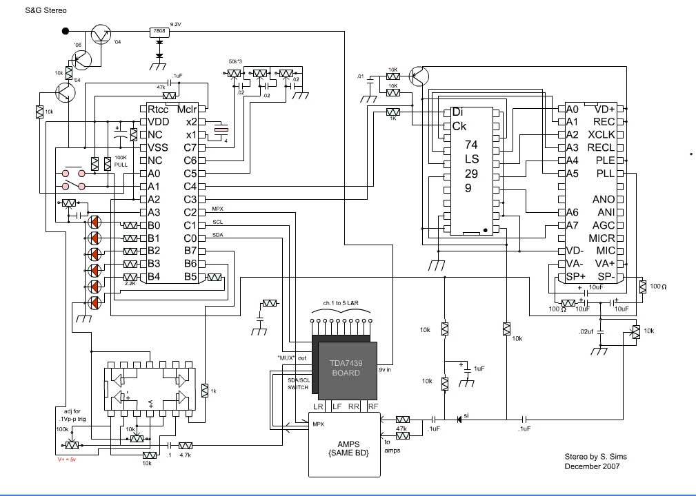
| Stereo Circuit Description: The PIC16F57 is the heart of control and user interface. To keep down complexity, one button is used for selecting 1 of 5 channels of stereo input to the EQ and amplifiers. Also the button, when held, enables menu selection. The switch ( also pulls to gnd ) is to turn off unit. In effect unit only goes into sleep mode to retain memory on menu settings. PortB,0-5 are to drive LEDs. PortB,5 is for on LED, while the other 5 are for channel selection and menu selection. Port B,5 also switches the inputs 4&5 making an extra input as the audio chips only have a MUX of 4 inputs. PortB,6&7 are set as inputs so program can write directly to the PortB without effecting other outputs. Port B,6 is the button input, pulled up by a resistor. PortB,7 is and input from the AutoSelect Amp which detects audio, thus informing the PIC to stop on present channel.( See programming ) The amp brings up a small signal ( adjustable ) to 10x then that signal is fed into an offset digital pulse amp. (Either on or off) As the threshold pot is brought up going into the (+) side of the op-amps, the sensitivity decreases. The audio supplying this amp is fed directly from the front 7439 chip's MUX output. This way there is no volume/EQ changes. The sub output is from a LM324 LPF tuned around 80hz. This is amplified via a separate amp, which is also tuned for the low end. The other 4 amps are 1 per speaker. The 820's are higher power so will drive the forward speakers. The 386's have a (-) input so will be good for the MPX audio on rear speakers.( explained further down ) All of the amps are the 16 volt variety so regulators aren't required, just some filtering. |
|
| The
TDA-7439 is a 3 band EQ, balance and volume Audio processor chip. Because
there are 2 sets of speakers, 2 chips must be used to optimize their audio
characteristics.( notice the way I said "must") The control interface for
these chips is via a 2 line I2C bus. The bus is switched from the front chip
to rear chip with a 4066 analogue switch for simplicity. The lines used to
switch this 4066 are also used for MPX switching, but data is sent quickly
enough so as to not disturb the MPX switch. ( Caps hold signal longer than
data/clock timing ) This is to save on components and additional current
draw of another logic circuit. Data for EQ/Volume/Gain/Attenuate (balance) is all configured by default prests and user presets. For example: When watching a movie, one wants plenty of Sub and highs, but medium midrange and bass. Alternately, if one is listening to shortwave, The sub should be off, along with the highs, but midrange raised for voice. Electronic dance music ( one of my favorites!) must have a rolled of low end, flat midrange, but raised high end. You get the picture. The MPX is also part of the presets. |
|
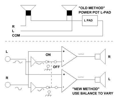
| MPX
MPX (as I call it) is where the 2 signals on a stereo amp, are configured to
cancel each other out. A 100% MPX would completely null voice, acting like a
karaoke null of sorts. That is because most voice tracks are mono. This
effect makes a very realistic back speaker feed. Drums will sound like they
are echoing off of the back wall because the reverb of drums is tight and
not in phase, thus stereo. |
 |
| After doing a test, I
found that this works fine, but on full MPX, care must be taken to filter
any "highs" beyond 12khz (I'm guessing) because any slight phase diff. on a
mono signal causes a popping occasionally. Of course MPX shouldn't be on for
a mono signal anyway! I am now also
adding in the ISD1420 recorder chip & programming so the menus will "talk".
I'll return to post more once more on that is done. Here is the next addition to the page. The
digital side of the s-layer schematic (in flash, click on stuff to open
others!) below has been assembled on a wish board, partially, and on a
"real" PC board for the 7439's. The original 7439 I wanted to use, and the
ones I received turned out to have 2 more pins! I thought oh no!! Good thing
I hadn't done the board yet, almost didn't notice it! The pins are a tap off
the MUX's instead of a bridge. I've updated the
datasheets.
Links to printable schematics are stereoTDA7439board.jpg stereoMainAmps.jpg stereoMainSchem.jpg (right click to save) Because I won't be the only one using this, and because I have made so many gizmos before, I have made a users manual. 16/02/08 As can be seen, the project has grown some... Sub: Voice menu: Auto-select: I am about to make the 2nd board so I'll be
posting the results :) Feb 20, 2008 |
|
to antenna switch |
 Stay in touch! |
to level sensor |