|
This song file is loaded to an attached serial SRAM (Microchip 8Mb) into a
specific memory area, and if it is 1 of a group of up to 8 loops, the other
"songs" would be loaded into the following areas of SRAM. Other data from
the original .MID file, such as time signature, orig.BPM, # of tracks etc)
is loaded to an area of SRAM that has song settings.
Process:
Once a BPM, or tempo, has been derived (from tap pedal, original BPM,
external Midi Clock, other inputs) the start of the sequence is pointed to,
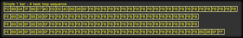
and the data is sent as a stream on to the MIDI outputs up to the next F8.
Once 1/24th of a beat (or quarter note) has passed, the data up to the
next F8 is sent. In this example there's 24 F8 pauses per beat, totaling
96/bar (4/4 time)
You may have notice the FD at the start and the FE on the start of each
subsequent beat? This are treated as F8's but are used to denote the start
of a bar, or a beat. This way, if a drum sequence is in a mode that a double
tap switches to a lead-in loop after the bar has started, the PIC only needs
to find the next beat without having to count all of the F8's.
Before being sent to the MIDI out port, these are changed to F8's. F8's are
used in standard MIDI streams as a (non-SMTPE) MIDI Clock, and although I'm
not sure, seem to be 24/beat always.
Calculations:
Even though deriving MIDI tap tempo from millisecond counts between taps
seems logical and sufficient, it's not. I learned this with the Tap
prototype. At 120 BPM a tap will have 500 mS between each. At 121 BPM it's
495.8677... which is quite a bit, 5 mS difference. But if using an averaging
algorithm, then deciding whether the tap tempo variation is within the "time
to change tempo" range it becomes a bit course. ( I discovered that a
variance range must be used if using continuous tap mode or the beat gets
faster and faster because of latency ha ha! )
Also, if the sequencer is stepped in 1/24ths of a beat, that 500 mS will
produce 28.83 mS per 24th. 28 x 24 = 480 mS = 125 BPM! So just numerically,
a higher resolution must be used. This is the main reason I chose the PIC
because I can write a sequential program that will count uS cycles
accurately.
Granted it makes big numbers (500,000@120BPM)
but it's required.
So a good
tap tempo -> BPM -> sequencer step example would be:
Tap has a space of 431,644 uS. The 1/24 (F8) step should be 17,985 uS. After
24 F8's, the time passed will be 431,640. This is 139.0047 BPM. If TAP is >
+/-2% ( 8,632 uS) from the 4 beat average, then change tempo by 2%. BTW That
percentage value should be user selectable I suppose, as should be the
"slew" rate of the averaging algorithm.
Real World Problems:
CC Rush Hour!
On this page, it all looks pretty solid so far, but
in the variability of a real song created by all sorts of software
sequencers, there's a variety of issues that came up immediately!
The most annoying to date is what I call the "CC Rush-hour". This really
resembles auto route management in a way that a "real" song will have many
instruments, and with each instrument many controls that need to be set at
the "rush hour" or start of the MIDI song. The most basic of these controls
is Channel Volume, Pan, Pitch wheel, Program Change (actual instrument #),
and sometimes Bank selects (2 of them). So that's 6 basic controls that are sent for
each instrument, which could be 10 or more. Now with 10 instruments that's
60 controls that need to be updated, before any notes are even sent at all.
Each control has 3 bytes, which at the MIDI port baud rate, takes almost 1
mS to send.
So, with just the basics of each instrument, we're looking at about 60 mS
to send all of the data at the start of a song (or loop) which is totally
unacceptable in a sync'ed sequencer. I had noticed when using my prototype
with FL Studio 10 that sometimes there'd be a delay, so I added pre-play
compensation that would actually start FL playing before the next tap! This
worked but it'd vary annoyingly from song to song (in the computer). After
some thought I realized this problem.
Some songs have 3+ lighting control channels with control counts from 6 - 24
each!
Jeez! One of the reasons why I'm building this sequencer is to do away
with latency and use pure hardware, but now the MIDI 38.25 K-baud is
sneaking up on me! Unbeknown'ced to many musicians, even USB MIDI built in
to keyboards/sequencers has to stick with the MIDI Baud rate so it's no
faster, just more cluttered as a rule...
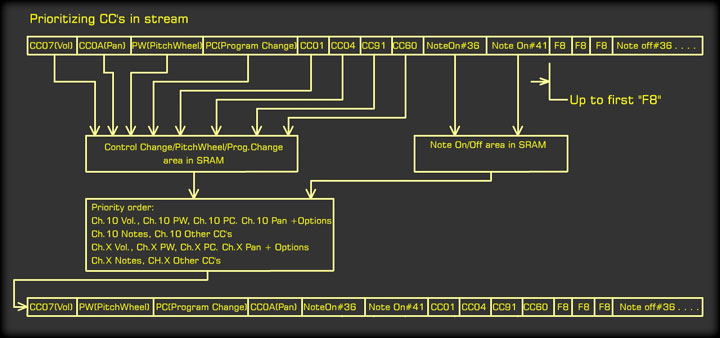
So my solution to this is to Prioritize by order:
The diagram to the right explains the method. Basically, take all of the
Control Changes and non-Note data up to the first F8 occurrence and save
them to a temporary spot in the SRAM. Then move the (if any) Note data
to another spot.
Now take the most basic control data and place it back into the sequencer
memory first, followed immediately by the notes of that channel 1-16,
then all of the non-basic (and hopefully less important!) controller
values at the end.
Because Drums being on-time and in sync is most important, Channel 10
will have priory over the rest, which will be loaded from 1-9 and 11 to
16.
Now the delay to the first notes will be minimal, with a max of 6 mS
latency, or 4 mS if Pan & Pitch wheel from drums is out of the "basic"
list. This will work great for songs or drum loops. The next channel's
notes (Ch.1) will be sent by 12 mS and so-on.
CC Stragglers:
The next problem is the stragglers, or CC's
that haven't been sent within that first 1/24th of a beat. The song
pointer should be at the next F8 once that time has passed, but if it's
not, then a counter must be incremented to show the number of F8's yet
to be registered and sent. At 120BPM, only 28 3-byte MIDI messages can
be sent, (because of the baud rate!) so if there's 60 controls, then 2 more F8 requests will go
unanswered before the stream catches up. |
 |
A good
solution to this if the song isn't a loop, is to "pre-load" all of the
controls at song-load time and send them before the song actually
starts. This could be done up to the next F8 as all of the control data
is always in that first space. Once the song *is* played, any non-note
data in that first time-space is ignored, and only note data is sent.
The above solution would ensure that the drum channel 10 still gets
priority if a note exists.
If the song *is* a loop, then a pre-load is probably out, as if there was
enough CC's to justify a pre-load, then when should they be loaded? Some
CC's may have bad affects on the end of, say, a snare build right at the
end of a loop! So the only solution is to keep the amount of CC's down
in a loop. Some loops have no CC's, if you export a .mid file from
PianoRoll in FL Studio, it only saves note data, no CC's.... which is
fine if you don't care about pan L/R or any instrument FX. This takes me
to the final part of "Real World Problems-CC Rush Hour":
Loop CC Declaration:
As
mentioned above, straight MIDI (type 1) exports will have no control
data. My sequencer will set Volume, Pan, PitchWheel, BankSel, and
Program Change to default settings when a song is loaded. If the folder
has more than 1 file to be loaded then the files are considered to be
loops, because 2 songs can't be in the same folder.
What if an override (MIDI) was needed to remove or add a reverb effect
from the drums? This would be logically done by saving the Drum "Intro"
loop as a full MIDI file. That first file would be treated by the above
solutions and saved as a .TAP file, along with the rest, but would have
settings that would stay the same for all of the loops. Makes sense to
me :)
This means,
the first, or "Intro" .mid file (not really a loop) must be saved from
the Software (FL Studio) as a song, not a piano-roll MIDI export. This
can be a bit of a pain as a drumloop imported to a piano roll for a set
of MIDI Out Drums requires that the MIDI Out patch volume/pan/Kit (PC &
banksel) etc be set appropriately for the loops that will follow, as
this will define the drums that will be used (Most MIDI drums have a
variety of "kits" selectable by the PC and bank selects). Some loops may
work differently and sound very different with different kits i.e. Rock
Drums vs. Conga Kit! For this reason, the loops should all be tested in
the same .flp (in FL Studio) to see how things will sound, and the kit
selected from that.
Luckily,
most "Kits" are standardized whereas "Kick" is the kick note for most
kits, and "snare" is a snare or snare-like sound. Cymbals can vary, but
usually to bells/crashes/splashes etc, and the hat generally remains
constant. This has been done this way to facilitate the loading of
different kits to a set of V-drums, even though they didn't exist much
in the 80's. Forward thinking!
SD Card Loading Tests:
A
test program to decode MIDI files, turn then into the sequencer files as
mentioned above, then stream the "new" data out have been successful!
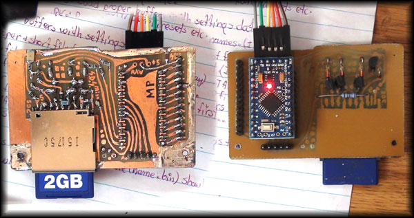
The Pro-Mini Arduino has been interfaced with an SD Card slot, and
loaded with a program I wrote (that was partially stolen!) with handling
long filenames in mind (That's filenames and directory names > 8.3
bytes) The output was just feeding to the computer which will eventually
be the ATMEGA.
|
As I upped
the baud rate from 9600 to over 115,200 baud, I realized the
bottle-neck was coming from the SD Card read, not the output baud
rate! It can load a decent sized song in about 5-8 seconds, but
that's too slow for my likings! Looks like I'll have to replace the
level shifter (5-3.3V) diodes and NPN transistors with FETs and do
it up properly. Oh well that board is a mess anyway! (photo right)
A small
note on Pro-Mini Product Variance:
You can see the FTDI plugged into the programming header with all of
the colors of wire. Eventually, I wrapped tape around all of those
individual female pins so I could use it to program a different
pro-mini for another part of the project by just plugging the whole
thing in. Brown to the right always.
I plugged it onto the new Pro-Mini I got in the mail that morning and
smoke!! It turns out the pins are all different! It ended up shoving
the +5V into the TX line (of course) and the ground was on the DTR
pin (I think) so no wonder! I can't show you it because shortly
after it met it's maker by way of a hammer and the vice in my
workshop! Oh well, they're cheap.
Now I always carefully check the image the seller has posted of it because
not all Pro-Mini's are the same. Some don't even have the A4 and A5
pins (between the 2 big headers) which is inconvenient if you want
to use the extra ADC's or the I2C interface!
Anyway,
the RX'ed data from my test song, then a complicated song by Brain
Adams (that has tempo/time sig. changes in it, not very good
for a tap-tempo based sequencer huh?) was saved as ASCII HEX and
after a few hours of checking it over, looks solid. Yay!! |
 |
|
Closing:
Once I have more data on the sequencing section,
build, *.ino's, I will post it here! June 15th 2015
| |
|
New Central
Controller Configuration
 |
| Yes!
I've done it again! I mean yep, i went and did it again. . . design
change. But the good news is it's permanent because most of the
boards now physically exist.
I had
originally intended (and purchased parts for) to use a parallel bus to
link to all of the peripherals, but as most of the peripherals are MIDI
related, why not just use MIDI?
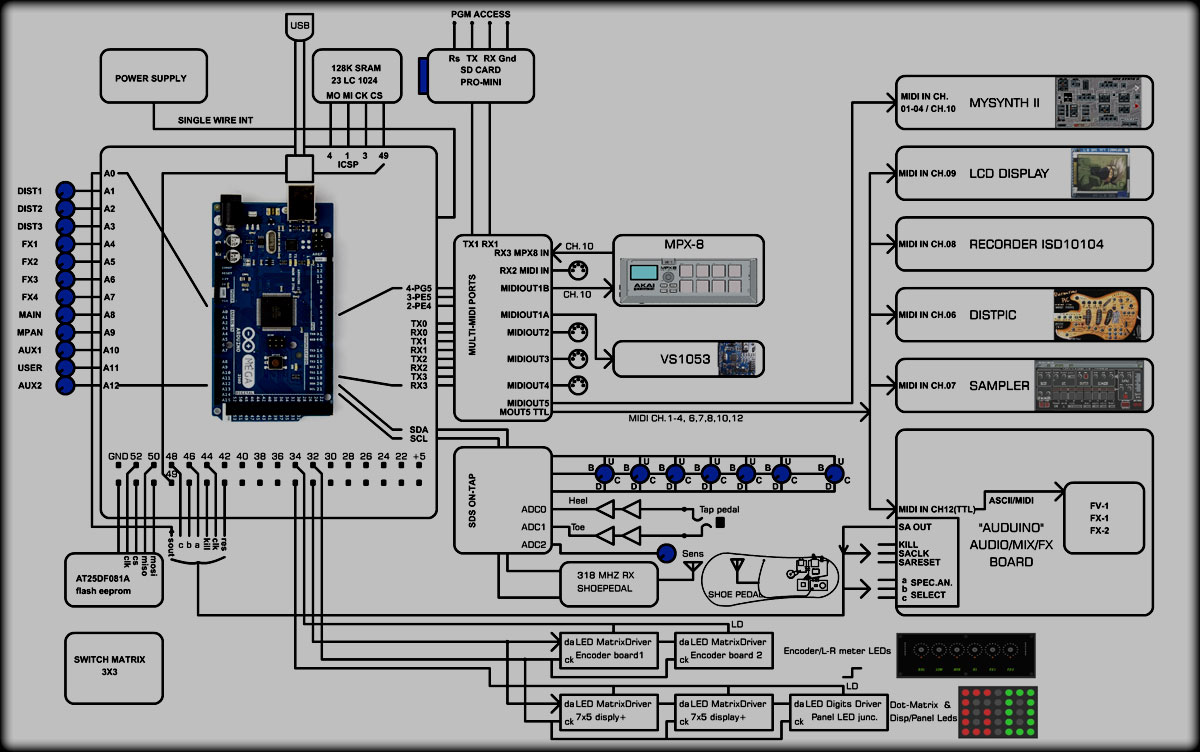
As can
be seen in the above diagram (I deleted all of the old diagrams) the
mySynth II, distortionPIC, Sampler, MPX-8, and VS-1053 MIDI synth, are
all or were designed to work directly with MIDI. I decided after I made
the mySynth II, and it's related FL Studio dashboard (used to create
presets) and realized how much easier this is.
|
|
So the
distortionPIC and
Sampler have been designed for MIDI on their own
channel. All of the "peripherals" connected to MIDIOUT5 are on their own
channels. This doesn't mean the channels feeding into the ATMEGA will be
those, just those channels will be used when the ATMEGA transmits it on
MIDI OUT Port 5. The input Port channels-->peripheral channels are
configurable as a global "stage setup" preset.
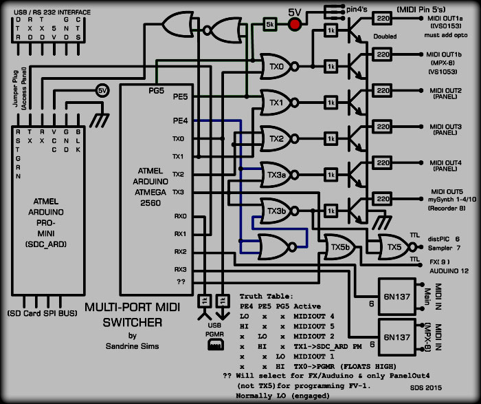
Oh,
that's the other design change, the ATMEGA 2560 is now the central hub
of the S.I.A.B. The interface to almost everything is through this
simple circuit (right). The Pro-Mini, which reads the SD Card, can feed
data at 115Kb (and maybe faster) into the ATMEGA's RX1 to be saved to
the serial SRAM as the song loaded.
Each of the 4
USART TX lines (ATMEGA has 4 separate USARTs!) is gated to be
multi-purpose.
TX0
sends MIDI Data to MIDIOUT1 and 1b which runs the VS-1053 MIDI synth,
and the MPX-8 (channel 10) simultaneously. The MPX-8's drum samples will
be on notes the VS-1053 ignores on ch.10. During ATMEGA programming, PG5
will float high, allowing the USB programmer to receive whatever is does
during programming without send "junk" to MIDI.
TX1
sends MIDI data to the panel MIDIOUT Port 2, but if PE5 is high, the
USART is set to a high baud rate and comm. with the SD Card Pro-mini is
achieved.
TX2
always sends MIDI data to the MIDI OUT Port 3, may change for more.
TX3
sends MIDI data to MIDIOUT Port 4 if PE4 is low, or to MIDI Port 5 which
is to internal peripherals mySynth (isolated) and distPIC &
Sampler (at TTL levels).
If ?? (haven't decided on pin yet) is set low, the the Auduino is
accessed. I've done it this way so during an FX ROM programming session,
no internal peripheral is getting swamped with data that will be
primarily RS-232 (Hex-ASCII). PE4 will also be low.
The 2 MIDI
inputs (one from the MPX-8 Drum Sample Player's finger pads) are fed
into RX2 and RX3. These of course cannot be active during an FX ROM
programming event.
|
 |
|
As for the
Pro-Mini to FTDI jumper setup, it's undesirable, and I'm going to work
at making it simpler. I want to be able to update a firmware without
needing to pull the S.I.A.B. panel off. The main problem lies in the
FTDI TX line. I have tried separating this line by using a 1K resistor
on the Sampler/Looper module and there's been no problems, FTDI is ok.
The only thing to remember is to keep the "other" line, from the output
of n OR gate in this case, high for the duration of the programming. A
menu command to pause the ATMEGA would be in order. |
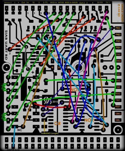 |
The image to the right is the USART board as per the above schematic.
The footprint has been matched to Shield over part of the ATMEGA board.
The output pins will be an angled header under the board (I guess) as
the On-Tap board will be stacking on top of this. The double header was
just for positioning. The SRAM will mount on this board, but the EEPROM,
an SOIC sized chip, will mount outboard off of the double header pins
that Arduino conveniently paired up with the SPI interface. Strangely
enough, the test SRAM was mounted there!
Granted the
board is a horrible mess of jumpers, and hasn't been etched yet. So I
might try to re-arrange it some to get rid of some of the jumpers. The "Auduino"
(bottom center) header had to be separate as an after-thought
because there's no more room across the top!
One day
I'll fork over the cash and get the real version of Eagle and let
someone else do the boards. Using Flash is versatile, and single-sided
boards cheap, but sometimes it's a real pain designing the layout
itself.
Well
that's it until summer is over
Cheers!
Sandy* |
|