I
have done some preliminary test of this circuit and it looks good so far.
The main issue will be to use identical LEDs, and place then in the exact
same way in front of the CDS cell. If there is too much variation it'll get
a "personality" which I don't like too much of. ( Like my
Light Strip Project.
Sometimes it wants to be bizarre and does weird things; never acts as
predicted! )
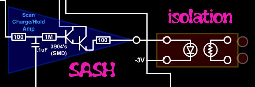
Another good point on this circuit is the wire between the SASH and the LED
can be long, thus allowing the LED/CDS couple to be local on the audio board
reducing digital noise potential in the box. A bad point is trying to
control stuff that needs a 3 pole pot, like an EQ design, means putting in 2
CDS cells that need to add up to a fairly constant value. Tricky dicky.
 |
Update
May 7th 2014:
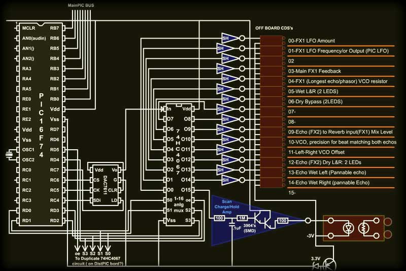
As can be seen in
the diagram, deciding on which CDS controls what is getting clearer. You
can see the DAC (12 bit) feeding into the analog de-mux. In order to use
the entire range over 5 volts, the LED needs to be pulled down some. 5v
-(.6 +.6 + 2v) = 1.8v max. So the cathodes will need to be on the
negative side by 3.2V. It should be adjustable though as it depends on
the LED.
This
board must be kept away (Or shielded) from the sensitive FX audio board
so the uP noise doesn't get to it.
The
distortion circuitry (below) will be driven by another 74HC4067, but
that may also reside on this board now as I've changed the circuit away
from analogue filters (for now hehe!)
With
this much control, especially over the echo or reverbs' VCO, a lot of
amazing effects can be created. For example, ramping the VCO with do a
pitch shift at the output. If controlled by a MIDI file, notes could be
made to "portamento" into the next.
Introducing a small square wave at the VCO can cause an octave shift. I
played with that for quite a while. Great for "space music" ! If a large
complex wave is introduced, the original input is so different that a
new instrument is created. Even a generic MIDI synth like the VS1053 I'm
building into this project, sounds great! Kept in sync it really
twists things nicely, sorta like the Kieran Fosters' VST dBlue Glitch.
Sweet! |
----------------------FV-1------------------------
FX
Update! June
9th 2015
Unfortunately (and
fortunately) I have found a better solution than the PT2399 for the FX
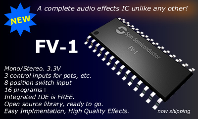
board. (Even after I made up all the boards!) It's called a FV-1 DSP by
Spin Semiconductor
This chip is
entirely unique that it is completely programmable (using their free IDE
software and an external i2c EEPROM) and even comes with 8 reverb and FX
built in!
It was designed by a fellow named Frank, and the Founder of Alesis /
inventor
of the ADAT, Keith Barr (who sadly passed away in 2010). The ASIC (App.Specific)
programming is a little hard to grasp at first, but gets easier as one
progresses...totally different from PIC or Arduino.
If
you're trying to decide on an FX chip, get it! I had to get mine from
Germany (Das
MusikDing), but it was worth the wait/$25.
Here's why:
It can do simple or complex (EQ'ed/filtered) reverb with all of the advanced
features that a VST may have, without the latency.
It can do real on-the-fly pitch shifting with a minimal delay, stepped as
chromatic notes, or sliding (like off a pitch wheel)
It can do FM and Chorus FX, it's main purpose, very well.
Left in and Right in can be split and are completely independent in the
programming, so one could do a pitch-shift and a reverb (quasi-stereo) at
the same time if looped back through an LPF.
It can do distortion algorithms and had I known of the FV-1 then, the
distPIC (below) PIC would've been controlling an FV-1 instead of processing
audio directly.
It can do all FX, tremolo, FMing, filtering (LPF/HPF/Notch/BPF with Q
factors), synthesis, and even sideband (I think I've figured out how)
inversion.
A pretty amazing chip!
| As
can be seen in the image, it's an SOIC sized chip, runs on 3.3V (a bit
inconvenient), and is open source. It has integrated 16 bit ADC's /
DAC's (sigma delta) which makes it easier to design around, 24 bit logic
internally, runs off a 32KHz clock xtal (or VCO), all the hard stuff is
done!
A bit of a
disappointment is the 3 pot inputs, 4 or 5 would have been nicer, but
there are ways around that. The EEPROM interface, allowing an extra 8
"programs" to be accessed, is limited to only 8 as the selector switch
is 0-7 and internal/external programs. Right away I decided to
circumvent this limitation by using a PIC chip to emulate a EEPROM. As
it will control the selector/internal/external inputs on the FV-1, it
will be able to send appropriate 512 byte sections of the PIC's program
space.
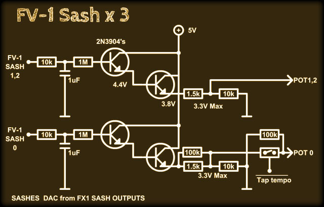
For the
SIAB project I will use the "Auduino" controller (FX Sash board) which
is already made at this time, and some resistors acting as level
shifters. These have 12 bit resolution so can be fine tuned if needed.
The knob 0 input will also serve as a tempo input that will be used for
certain FX I plan to program. Echo in sync can be desirable as well
right?
The 4066
switch (Tap Tempo) has been replaced by a simple NPN transistor, but
could be hacked back over to a spare 4066 switch as 2 are already being
used to switch out the feedbacks, just to be certain! The CDS photocells
can go in excess of 1 Megohm but still a very small amount will trickle
through, and depending on the program running in the FV-1 could cause
issues. The 4066's are of course decoupled at both ends, being
single-supply. |
 |
As
can be seen in the diagram below, the outputs are also using CDS cells
to control level to the Main Bus and Aux Bus. These are almost just a
secondary level control as the FV-1 can do all of that from a Pot as the
"Wet" control, but if I want to pass the FX output through the Post-EQ
(return EQ) first, the Main Bus will need to "disconnected". The Post EQ
is yet another TDA-7718, which makes 8 of those total in the SIAB. (One
in the DistPIC
Module, this one, and
6 input channel EQ's) The inputs are directly from the mix of
those TDA's LR/RR outputs so any input channel can be fed into the FV-1
at any level, even separately (I plan on running some FX as FX-1 & FX-2
as before) |
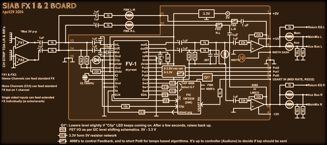
Final FX board design using FV-1 IC, a
PIC18F2539, and LM833 super low noise dual op-amp. |
|
What's
really amazing about this chip is the low noise / high frequency
response! With a 32 KHz Xtal (resonator) it can still sample at that
because it has internal frequency multipliers (runs at 32 Mhz I
think) and with a sample rate like that, the nyquist thingy dictates
that it's useable up to 15 KHz or so, which is plenty. If a higher
freqency Xtal, say 44 KHz was used, it'd be at CD sampling rate, but
delay memory would be somewhat less. The delay memory at recommended
sample rate is 1 second. Plenty!
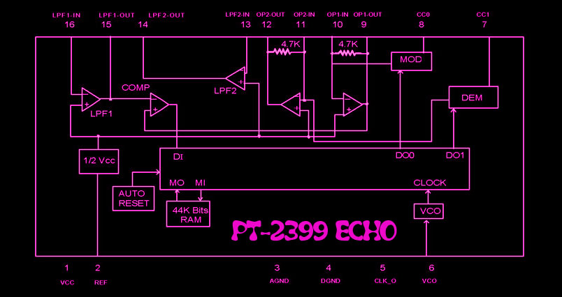
The
PT-2399 (top of page) is fine for guitar and background reverb FX
but
1) For reverb several are needed+echo, and that's at 30mA per, so
total draw at 5V would be 210mA (7 of them). A lot!
2) The cut-off is around 4 KHz max, so not great for 'verbing
sizzling vocals. I tried, it just wasn't there.
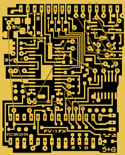
As
can be seen to the right, the board layout is a nice compact
vertical (off the "Auduino" mother board) that will have a right
angle pin header. The 24 pin PIC18F2539 is through-hole mounted as
there is more room on that side (clears surrounding boards) for the
required socket so it can be romoved for programming.
Programming the DSP EEPROM emulation memory will be easily done as
the flash PIC's have "self programming" of program space, almost the
same as their built in EEPROM space. This chip has 24K so I'll
likely use 20K for the FV-1 programs. That makes a cool total of 48
individual FX. Some of those may be duplicated with changes to what
the 3 "Pots" do.
The
only thing I haven't decided on is whether to send hex files via
RS-232 to the "Auduino" pro-mini chip to send on to the PIC via it's
USART RX, or to have the ATMEGA (Main Hub) read the programs off of
the SIAB SD Card, then decode & send the data to the "Auduino",
which in turn relays it to the PIC. The code (an image ASCII
HEX created by a Macromedia Flash routine) could also be be directly
pasted into PIC MPASM during program time, which is a bit
cumbersome. So many choices!
Finally, you may have noticed a "Width" CDS in the diagram above.
This basically mixes the left and right channels using an external
SASH drive from the FX Sash board. Kinda crude, but it'll do the
job. Using 4 op-amps to do this is just a waste I think! |
 |
|
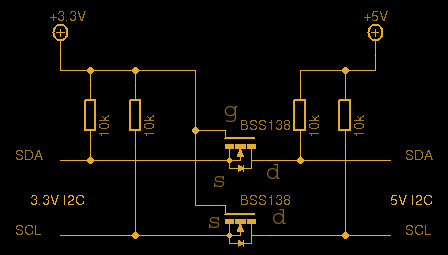 |
A
small issue that needed to be addressed (well not small if ignored!) is
the logic voltage of the FV-1 vs. the PIC: 3.3V & 5.0V. I was thinking
about using the diode method, but because of uncertainty on how the FV-1
pull-ups would react and how it handles the ACK, I found this nice level
shifter using tiny FETs. Wow, why didn't I think of that?! Now I'm going
to re-design my SD Card reader board as this could double the speed.
Anyway, I
think it was posted by LadyAda from Adafruit, so kudos you guys! ( I
bought one of your "Trinkets" to celebrate! ) The BSS138's were
purchased for this specific purpose, which I almost NEVER do, so that's
saying something.... it'd better work, I bought 10!
The
inputs (switches and pots) are just using resistors as voltage dividers
because speed isn't crucial at all with those. The PIC selects
"external" then the address (0-7) of the program. This causes the FV-1
to try reading the I2C bus, so the PIC must be a Slave. |
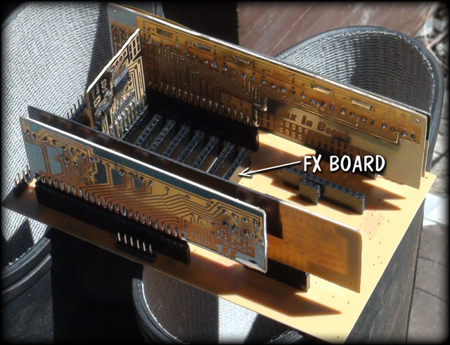
| To
the right is a photo of the "Auduino" mother board, (sitting on Gena's
workboots!) and an arrow pointing to where this board will be. A fairly
tight space with not much on either end for room. The height is over 2"
though, which won't be a problem for clearance beneath the panel, but
will need to be braced on it's own (so it doesn't "unplug" from
vibration) being so much higher than the other boards.
The SASH boards
aren't yet joined together in this photo. As with the MySynth II the
CDS/LED pairs will project through the board through holes in black foam
tape. The LED inside board is painted black to minimize stray light from
the adjacent LED and the outside world.
Because
the FV-1 uses 4 SASH circuits, and the 4 PreAmp SASH LED/CDS pairs are
on another board, the CDS board is much shorter (closest in photo
right). |
"Auduino" motherboard with some SASH cards
installed. The small board is a TDA7718 channel |
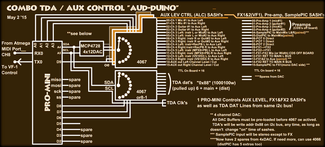
Above is the
final "Auduino: SASH control configuration. It can no longer change as the
boards are done! The AUX taps are for secondary outputs (can be back room or
stage monitors, or both!)
"PLY" on the panel is now
"Pan
Level
Y" and AGC
is "Aux Gain Control"
, both for the AUX1 output. The Aux2 output is controlled by
the MainOut EQ
board.
Once again
everything (the board draft) has been done is Flash MX. I don't know how I'd
live without it. Maybe one day I'll switch over to Eagle, but
not
today!
The project (and all projects) is on hold until after summer, but check back
often in September 2015 for more! (June 2015) Cheers, Sandy
Distortion
PIC This
next section will cover the progress on a distortion board I call the
DistortionPIC. I did some experimentation with a PIC16F74 and a DAC08E
that's been sitting in my parts drawer since the beginning of time. After
hooking it up to the PIC and writing a program to basically feed the ADC
input through to the DAC, I was amazed that it still works!
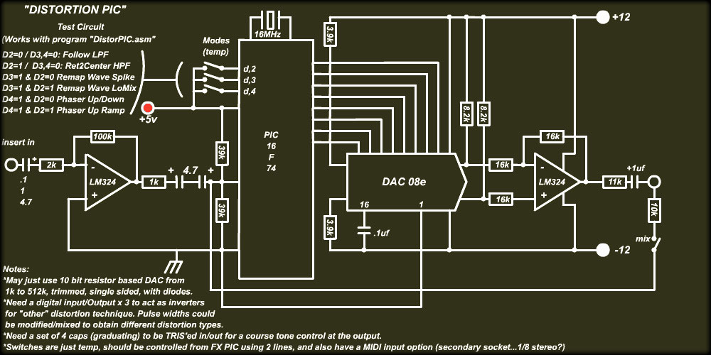 |
The
schematic to the left is pretty much exactly the way it was on the wish
board. Let the fun begin!
I wrote a
sloppy DSP routine to act as a low pass filter and it worked pretty good
so now the confidence is up. I tried modifying the waveforms using a few
tables to replace original values and came up with a nice smooth
distortion eventually. This is all new to me keep in mind.
Next I
tried making a delay the phases in and out by saving 128 bytes into RAM,
then starting a second pointer that would vary and ouput in a loop, like
a temporary formant. Got some pretty cool FX! But not what I expected.
The
sample rate runs at just over 30 Khz with 8 bits. I've never run a PIC
ADC that fast either. The last bit's dither was audible, but it *is* a
distortion board, and there should be some form of gate on it, just like
most good guitar amps have. |
| Before
I pulled it apart I got some recording of it during various test stages. I
shrunk it down to be shorter and it's
here,
(the completed design samples are
below)
The
original idea, before the ADC was to use the PIC chip as a sort of CMOS
buffer, which is ideal for distortion, but that's a bit too static for
my liking, so using several I/O pins (highly sensitive as an amp will do
the same thing. With added advantage of being able to control the
dynamics with slight delays an a few caps that can be switched in/out,
it becomes more appealing. |
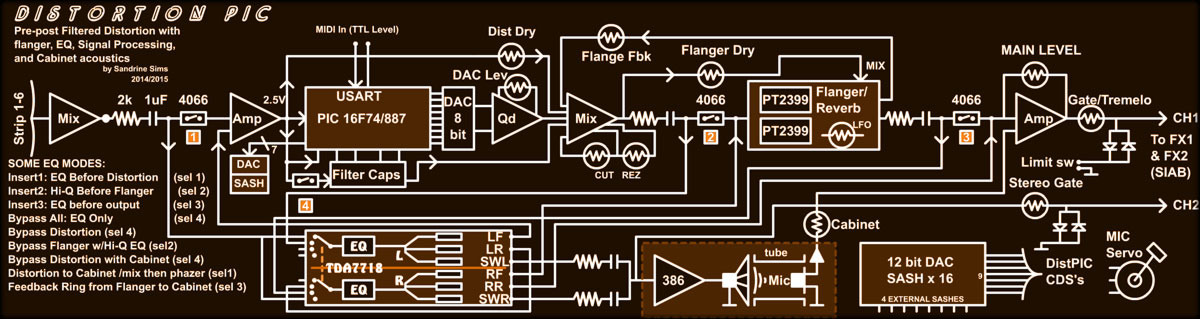 |
This diagram
shows a (yet another!) TDA 7718 being used primarily as an EQ. The good
part of using this chip is that it can be configured to be in different
parts of the circuit! Having EQ before the distortion can be desirable
to break away from the strip EQ, then mix it back in at the main output
with/without reverb/echo FX. The TDA chip has 4 fixed midrange
frequencies:
500 Hz, 1kHz, 1.5 kHz, 2.5kHz. Plus a variable Q of .75, 1 & 1.25 on
that band area. There's also a Loudness control with 400Hz, 800Hz,
2400Hz add/null, and the bass 200Hz level + 4 Q factors that might come
into play. Anything below that would be useless. The "frequency" of the
chip can't be changed either. The TDA 7439 (no longer avail.) had ext
caps on it's EQ.
Will this be enough? I don't know! Only experimenting with a guitar will
tell.
The plan is to
have tweakability on this board, but also a nice set of presets that
will set everything "just right" to get a certain sound quality! |
|
The EQ modes,
will allow for some flexibility by the position it's inserted at. The
first insert, just before distortion, will change the dynamics of the
distortion for sure.
At insert 2,
the left side output is fed back into the Right side input, thus
doubling the EQ's peaks or notches. The EQ would sit just before the
flanger in this case.
At
insert 3, the EQ is placed at the output. This is also a great place to
have a filter. There's 6 other obvious modes the circuit can be
in, but you may have noticed the LM386 off of the SW outputs? This is to
simulate a cabinet using a speaker and a mic. The audio is sent down a
PVC tube, then picked up be a mic. The mic's position can be changed
directionally which should change the dynamics. This might be manual or
using a tiny stepper/servo. The 386 may have a filter (CDS-C) on it, not
sure.
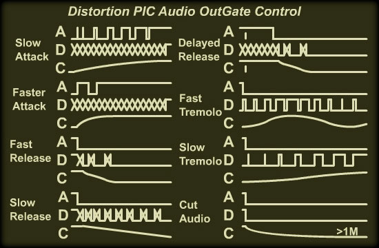
The
gate in the circuit is controlled directly by the PIC. The waveforms to
the right explain the various ramps of Attack and Release, and the
tremolo. The 47k resistor and the 1uF cap will limit the Tremolo to 20
hz, which is way faster than I ever use. CDS cells can go to a very high
resistance, >1 Meg, but after initial darkness, can take 2-3 seconds to
get there. It seems to change from one to another, but keeping the
impedance of the circuits using these low will speed things up and stop
leakage. In a worst case scenario, the 4066 switch at the feed, or the
output from the TDA7718 can be attenuated at "gate" time. I like the
smoothness of CDS cells in audio circuitry, no "clicks", and if the
slope is right, feels very professional!
Finally, the
whole thing is controlled via the FX PIC using some sort of serial
interface. All of the CDS cells are controlled from the DAC on the FX
PIC as well. In fact these boards might be stacked, not sure yet. |
 |
SO everything will
probably be changed again, but hey this looks pretty nice at this moment!
Cheers! Sandy*
May 7th 2014
|
Update June 4th 2015
The above
design turned out to be the best design, and I'm glad I stuck with it.
The DistPIC module was completed way back in February. And I couldn't
stop playing with it! Good toy.
After some slight modifications, only 5 SASH's remain to be useable
off-board, mostly because of the new stereo output control and gate.
I've changed the schematic above to update.
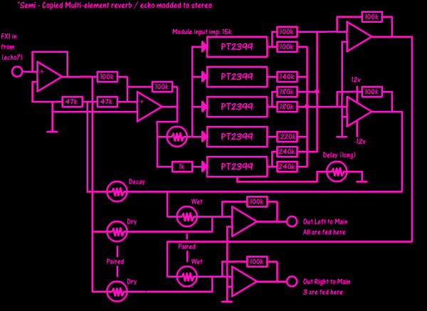
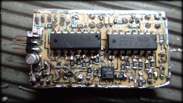
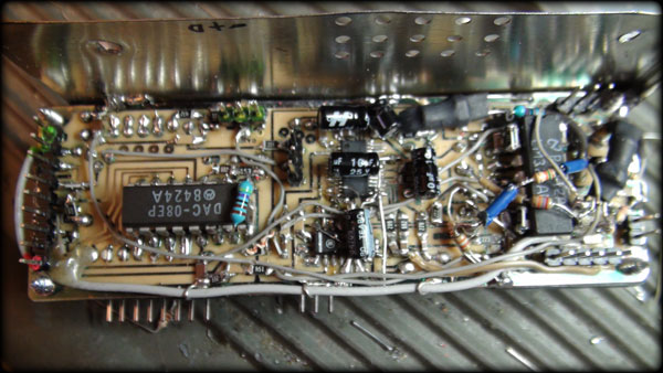
Below left
is the photo-etched PT2399 FX board. This yields a phased output for
delays, reverb, phasing etc. If used with CH.2 output, it's stereo. The
mix happens in the SOIC 4558.
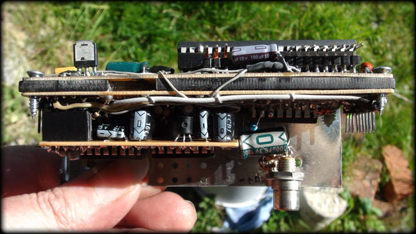
The photo to the right shows the whole thing put together. The top 2
boards are the SASH LED/PIC and the audio CDS side beneath it. The small
bottom board is of course the PT2399 board. |
 |
 |
|
If you look
closely, the mess below is kinda crude. This is what happens with
proto-types. This is before the other board stacks over it and hides the
worst of it. It's all ok as long as it stays working! The photo below
right shows the arcrylic black paint my neighbors lent me to block out
the light from the LED-CDS junctions. 3 coats were needed, but inside
the dark bowels of the SIAB it's probably not an issue. I had it sitting
out in the studio for quite a while as I started the Sampler project
just because hardware guitar distortion totally rules over a VST (I'll
never go back!) |
 |
 |
|
If you don't
believe me I've posted some samples below. Of course those have been
recorded digitally, and then turned into a muddy .mp3 so they won't
sound nearly as good as the "real" thing, so I guess you'll just have to
come to one of my shows! |
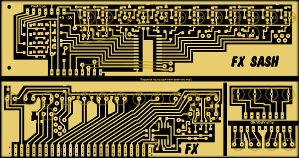
|
Anyway,
here's the original board designs that were etched. Don't go copying
them to make your own, because they aren't very accurate. Traces
were cut, circuits were added, others were removed, it's totally not
the same. Maybe one day I'll amass the pages of scribbles and notes
and draw up a proper schematic. If I was getting paid I would
tomorrow, you know how it is.
The upper
board has the 40 pin PIC16F887, (I like because can self-program,
good for the 128 presets the distPIC has) encompassing the external
SASH circuits, and the 16 SASH selector (4067). The right side of
that board has the LEDs (602 size LEDs) facing down through drilled
holes marked by the circles. The hole drilled removes the "short".
If you look hard you can find the 6 pin 12-bit DAC. I love those tiny
things! (It's just above the word "DEC") unique address I2C
happiness!
On
the lower board you can see the TDA 7718 footprint, next to a 4066,
and to it's left an 8-bit DAC. Sample rates make up for the low bits
and it is after all a distortion board. To the right of the TDA is
the now never-to-be-used-again-in-an-audio-circuit LM324 footprint.
It turns out the 324 has a nasty noisy crossover point at zero volts
(as this board uses +/- 12V) and I ended up having to offset it by
+6 Volts to make it stop with the "crackle" on lower levels. |
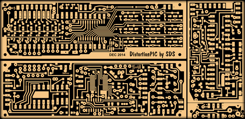 |
The far
right board, which wasn't modified much, is for the 2 PT2399 delays, and
the bottom tiny board is for the LM386 500mW amp to drive the cabinet
speaker. This is mounted in the lower section of the SIAB Box. See?
pretty simple when you break it all down. |
|
What's tricky is understanding the changeable circuit configurations.
The distPIC can re-configure it's circuit 8 different ways. To simplify
this the user manual breaks the circuits down into their actual function
by way of 8 separate diagrams. These are in the
Users Manual.
I've taken to creating a user manual for each module, or part of the
system, because it's a lot to remember!
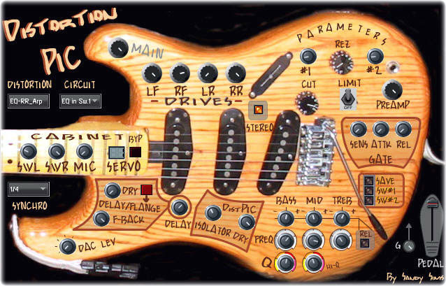
Creating an
FL Studio DashBoard for it was a very good idea, although it doesn't
explain how the circuits are configured. It does give a good visual
interface.
Once a
preset has been saved to the distPIC, it will configure the settings to
exactly where they were. A loaded song in SIAB need only have the preset
(0-127 above dashboard window) number and assign the panel knobs as the
song requests.
The
pedal control shown (standard MIDI CC#04) can connect with a real pedal,
or be used as another preset setting. This dashboard is the most stylish
one I've ever made, and yes it seems easy to control.
The
only real issue is the servo. After a preset is selected, the servo
won't adjust for about 5 seconds, so it's not flicking back and forth
wearing out as preset knob (if present) is turned. The main problem is
it creates quite a power surge which can be heard if connected to a big
amp. It's a short, deep buzz for 1/2 second. If the servo isn't required
(no mic movement) then the bypass button can be turned on by the song
sequence before the preset is changed.
I never thought this would be an issue, but changing the way a guitar
sounds during a song is amazing! For example, going from British
distortion to a smooth twang for the chorus. Wow!
|
 |
OK
the moment everyone's been waiting for, the samples! Please keep in mind the
audio connections where unshielded alligator jumpers for some of this ;)
The Samples are as recorded off the mixer in
Reaper
(an awsome DAW software I now use in place of Sony
Asscid
Pro) unmodified with any post FX etc.
There's so many modes and configurations, (21 modifiers, 15
Types, 8 configs) it's hard to understand without reading the user manual,
but I'll try to explain what it is you're hearing...
**Digital Processing
Modes**
Retro bit, Retro Sample Rate, Digital Phasing, Wave Riding, Fuzz, etc
etc. Lots of digital toys to modify the feed!
Here is a potpourri of
short samples, too numerous to list.
Excuse my 14-year-old heavy metal technique, that's only where I'm at so
far with electric guitar lol! |
Drums
Masher!
The distPIC isn't only good for guitar! Listen to what it can do to
drums. I announce the Type/Modifier for each. The drums are from a GM
Kawai set (not the best for sure) but you'd never know it now! Some
digital processing modes are in this (fairly long) sample along with EQ,
delay, and various Types. |
Mono to Stereo Twang
The distPIC was originally to be mono, but I couldn't resist tapping off
to make it stereo. The 1st strums are mono, the rest is stereo. You may
notice it's on the verge of distortion. That's because this is a real
miss-use of the distPIC hehe! |
Noter Type
This is a really basic use of "Noter". It'd be best used minimally at
the end of a solo perhaps? Too much is too much with this unless you're
into Thrash or Machine music. I think it's freakin' awesome! It's just
notes controlling the EQ+outs. |
Tremolo
This is a clean sounding Tremolo. The tremolo can be sine, ramp, or
reverse ramp. The tremolo can sync with the tempo as well which is
sometimes desirable. |
Mono to Stereo Bull
Beef
Distortion
Another mono to stereo clip. Notice the higher dynamics sneaking through
even though the distortion is very heavy? This is because of multiple
paths (and serendipity!) to the output. |
Noter Wawa
A short sample of using Noter (or Arp) with same test beat but in Wawa
Type Mode. In a song sequence there would be more variety of course.
I tried a synth into this later on and OMG! |
Jump
The function of the Jump is to change the dynamics of EQ Bass and
Midrange, but only during moments of "silence". It scans at LFO rate so
can be predictable. The controls are extreme for the example. |
Clean
Auto-Wa
I made up a little song to demonstrate the "Clean Flange" circuit config.
Notice the "boxy" sound of the guitar, and the mild, almost
imperceptible flange behind it. |
RR Arpeggiator
With another instrument, using RR Arp (level Arp) makes a guitar almost
synth like. If I knew better how to play, this would be much more
intense, but you get the idea! |
Retro & FM
Retro bit mode (not retro sample rate) is used to tin up the jabs at the
first part of this sample, then a drunken FM chorus takes over. The
delay is being controlled by audio level to the ADC, always a fine
effect. |
EQ
Arpeggiator
The idea of arpeggiating the EQ controls came to me when setting the EQ
in FL Studio to change with the beat. Why not just make it a Type? So it
is and here's what is can do!
"Noter" can do more than this, but needs a song to control it. |
Noter
Blast
This is a mono-chord demonstration of how "Noter" can twist a pluck of a
chord into something pretty cool! As I play, I can get into a groove
with this, but the limiting factor was the piano playing in the
background so I had to stay on that chord. It makes for an
interesting sample though. |
Synth Feed
I decided to pin a key down on my Korg and feed the audio in so I could
play with the distPIC to see what kind of sounds I could get The first
part is a "whistle" sound, which is run through the note-shifter, and
the rest are full-bodied multi-octave notes. Once it sounded nice the
notes change. Most of this sample is using the EQ-Arp, but has been
chopped up to make it shorter as I was playing for quite a while! Sorry
about the annoying drumline, I was testing for sync mainly. |
Cabinet
(Speaker/Mic)
This short mix of samples were created while testing the cabinet
feature. The servo turns the mic away from the center speaker which
changes the dynamics. When mixed with electric signal, some nulling can
occur. I've just changed the speaker, so not sure how that will affect
the overall results. The mic had to be turned up too high and would
cause feedback from the big amps. |
Users Manual |