| Day 393 |
 |
Dash Frame, latches, Hot
water |
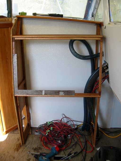
| The dash is well under way ( photo above ) but has the illusion of being curved. It is straight but something with the perspective distance and the angles on the dash give it a curved appearance. Curves are good on a boat! | |
| I was checking to make sure everything was
still square as that will make fabricating the large panel easier. I was
almost ready to put in the plywood on the side when I realized Gena
needs a certain size hole for the breaker panel. We have a nice panel we found on eBay with a picture of a boat, a big meter and lights. Something like on star trek. Problem is the breakers are the push in style and can't be shut off. Gena doesn't like that much so now it is her job to make a panel with square holes to accommodate the square switch style breakers. The new Dymo label maker will help in this case. Too bad the labels don't stick to rubber on wire. Hmmm. Lots of wire. The panel will be "capped" with solid oak cut into a curve as I have done in many other areas of the boat. The kick panels below were fashioned to slice in at 20º off 90. This is so the wheel can tilt in and gives more foot space. I had to pop the frames forward and sand off the excess (below) because a flat frame is needed for removable panels. Sanding is slow but the planer is still dead, and radial arm saw getting too old to do angles lengthwise. It has sat outside for 13 years, built 2 houses and almost a 45' sailboat. It deserves respect. |
 |
 "Kick plates" for dash |
| Sanding, jigsawing, and sawing in general is forbidden in the boat now because of the dust factor. It is a bit slower needing to come down out of the boat and do it all on the porch but there is more room and I do have a nice tan coming on! |
Anyway, we thought our problems
were solved until we had a look at the wiring in the water heater. It is all
barely big enough to handle the 10 amps at 120 VAC and would just burn off
at 50 amps. The connectors on the thermal switch are quite small and are fed
through with tiny <1mm rivets! This isn't going to work. The contacts in the thermal are likely rated far below 50 amps as is the overheat protection fuse. Gena was starting to search online for a higher amp thermal switch when the idea hit me! Why not just use the thermal and fuse to power an automotive solenoid? Duh! Anyway, $50 later we have the solenoid and Gena wired it all in. |
 |
| Above is the schematic which is simple enough. The load diverter will switch here as will the manual for 12 minutes max. Good idea. We must remember to put a beeper across the thermal ( skipped in the schematic too, lucky I am writing about this! ) so we know when the water has heated to max and the load diverter is no longer diverting. Another good idea. Speaking of beepers, you may recall the bilge pump setup panel had a beeper added so we would know when it is going. The beeper warbles strangely when running! I figured out that the problem is the beeper is basically hooked across the motor. High torque motors can actually send a reverse AC pulse of energy back when the next section of the stator makes contact. It acts like a generator of sorts for a brief moment. The only good way to eliminate this problem is to put in a reverse rectifier. We kinda like the sound but I think we'll try the rectifier in the main bilge circuit. That'll allow us to distinguish between the two if we're outside and it goes off. | |
|
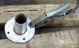
Being extra energetic, and having the plasma
cutter and welder out for the first time since last summer, I was going to
ask Gena if there was anything I could fab up for her. She already had the
parts out and was going to ask me ha ha! She was contemplating the exhaust
system and had picked up some stainless flex pipe for the muffler. Just by
luck, some left over pipe from the sprit was exactly the size needed to make
a flange for the flex. She was looking for some 1/4" S.S. plate I could cut
out and weld to the pipe, and found a pre-drawn template made from the
flange that is on the hull. What luck she found it! I promptly cut it out
and welded it together. |
 |
| As can be seen in the photo it fits the other flange nicely. Isolation is still a concern, even though we forgot about it for about a year. Some countersunk isolation washers that won't melt under the extreme heat are next on the "search for" list. This will stop electrolysis between the engine and the hull, if the engine becomes connected somewhere else. My idea of using a relay to connect the alternator to the house power ground may be used instead of a rectifier. This way the ground will only be bridged while the engine is running. We'll need to see what the alternator manufacturer says. |  |
| If a person sat down
and figured out which metals cause current flow which way, the whole
electrolysis problem could be solved by applying current in a desirable
direction. We probably won't go that far as it would only happen while the
engine is running and, after all, this is a sailboat!
|
|
Day 393:
11 hours - Continued with dash, made test latches and exhaust flange,
hooked up water heater
to DAY 392 |
NEW! The Big Sailboat Project Forum Come sign the guest book! leave comments, links, more! |
to Days 394+ |
|