| Day 392 |
 |
The Dash through-hulls |
| Day 392 |
|
The Dash through-hulls |
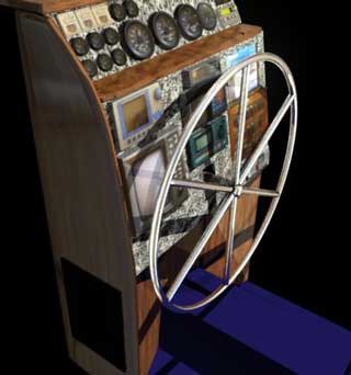
| Above is a picture of the dash. Oh no! Not now! As it is projected to be constructed in the near future. If it came out exactly like the 3-d rendering I created in computer world, we would be very happy indeed. I will endeavor to build as close a match as possible. | |
| Computers can be a real pain sometimes (
as we all know ) and drive one to the brink of self annihilation
occasionally, but in this case are a real help to bring ones thoughts
into tangibility. Also, creating all of the elements dimensionally
proportional to each other, i.e. the radar, gps, sonar etc., rearranging
them is as easy as dragging a file with the mouse. I rearranged the
layout probably 10 times after I had the dash panel layout
finished. On paper that would have taken days.
As mentioned before, a CAD program may be more accurate as it is tooled for designing real world objects. I just never learned it, and besides, CG is prettier! There have been lots of considerations in this design and much thought on the subject ( by me at the research stage and Gena at the "approval" stage lol! ) most of which is far too in depth to cover on on page. As the project progresses it will all be laid out for you to enjoy ( or jeer, laugh at, etc. ) |
 |
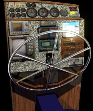
| Space was a landmark factor in the design. Is there enough room to put everything in? Originally I wanted to add the battery monitor panel and the load diverter panel as well. Gena said " no way, there won't be enough room! " She was pretty correct on that. There is some space left for small things, but not those big plates. (day386) | |
| The radar is on the left side so it can be
easily seen by peering in from the cockpit. Same with the Interphase
Twinscope depth sounder, even though we have a simpler one mounted in
the cockpit already.
The shape of the dash is also important. It can't go down to low as one won't be able to reach parts of it when sitting. Also the wheel must tilt so one can reach it while sitting, and it's out of the way when standing. The center underneath must angle in or the wheel will have a short trip while tilting downward. The "hump" houses the steering pump. It could have been mounted behind the wheel, but the tilt would require longer hydraulic hoses, not a good thing in a non-powered system. It's also good to get up on to the chair, which must be quite high in order to see out of the pilothouse window. Originally the whole pilot area was going to be risen by about 1 foot, but Gena wanted to be able to stand and steer as well. This makes sense as sitting can be a pain in the butt...literally! Enough on theory, I'll never get the page done! I started the frames today based on the angles and dimensions in the CG program. |
 |
 |
They don't look like much now, but
once in place will transform the pilot house into a "pilot" house. The one
side is much shorter than the other along the top because of the curve of
the dash. Each section is glued and screwed together for strength.
|
| As you may have noticed, the
pilothouse is looking much cleaner. We cleaned it out yesterday ( which took
a whole day ) and put things away, took tools, materials, and garbage down
that we no longer need. It sure is nice to be without the clutter. A new fitting was added for the forward bilge pumpout. This was going to go into the waste water standpipe, but there was concern over how fast the water would come out when it basically needs to push down water through the long pipe. Also the nipple would have been smaller that it should have been. It seems to be a simple solution to run it out the side of the pilothouse. Notice the loop to stop back flush from big nasty waves. These hoses are all behind the dash, but not to worry, everything on that side is intentionally there because it is shallow. The large clump of wires mostly goes to the switch panel then the breaker panel, which is also shallow, and the rest go aft for the cockpit speedo, depth sounder, aft breaker panel, and radar arch via a large tray made from vinyl eavestroughing Gena mounted today. ( photo below ) |
 |
 |
|
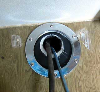
| It's time the through hull senders were mounted, and Gena took on the task. You may remember back when the box was built to house these just in case one ever failed, water would only fill the box, not the whole boat. Because of the confined area she needed to work in and the large nuts on the sensors, finding an appropriate wrench to tighten them took longer than the actual job! | |
| Some rubber butyl was run
around the large interphase sensors' shaft, then another softer butyl ring
around the outer seating. It seems the thing won't seat totally flat (
probably because it was used with a shim before on another boat and the
shaft is no longer 90º, or the holes aren't lined up, one or the other...)
It does come close though, and likely won't be a problem. The "slit" should
be filled with something to stop sea creatures from entering and making it a
home. I don't think it would be a very good idea to torque on it much more.
|
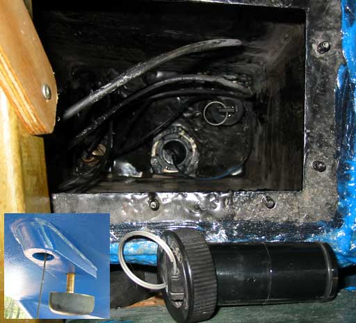 View down into "the box" a tight space; units ready to go in (inset) |
| While the boat is at anchor, the top of this pipe is well above the waterline level, but when excessively healed over, it may dip below. Stopping water pouring in, especially from the waste pipe, seems paramount. | |
Day 392:
7 hours - Installed through hulls for sonar, knot meter/ water temp, forward
scan sonar, made side dash frames
To DAY 391 |
A Vibration of
wire.. New Fresh, New Nelly  "no strings attached" coming soon! Summer '07 |
To DAY 393 |