| Project 46 |  |
Pedestal (Binnacle) |
|
||||
|
|
||||
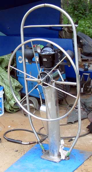
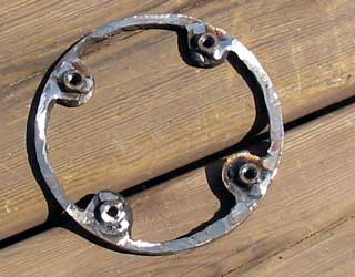
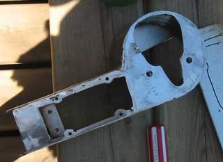
| The base must take on a pleasing
shape, but be functional. The 2 "ears" on each side were cut out to attach
the handrail that goes around the whole thing to. This hand rail will also support a display screen and partially the compass. |
 |
||||
|
|||||
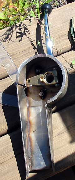
| The shift and throttle for the engine, I decided, will be mounted on to the side of the pedestal. This way the cables can feed down through the same hole, and the handles won't get in the way of the seating. |  |
||||
 |
Devising a
method to do this took more than a couple of brain cells, and much
humming and hawing as I put it together. The main things I had to remember were: (1) The throttle assembly can't be put together ( because of silly engineering) inside the "box" so must have a plate and cutout large enough to insert the whole thing put together. |
 |
|
| (2) There
must be an access panel below the arms so the cables can be
connected ( if they can't be connected and stuffed into the top
hole!) (3) The panel must go low enough to allow clamping of the cables to the mounting plate using little nuts and screws. (4) The cable center ( off by 1.5" from the handle's pivot point) must line up with the center of the pipe, but be far enough aft that the cables are aimed towards the back of the pipe to avoid the chain. (5) The hole in the pipe must be long enough and angled in to allow a smooth flow of the cables as they head in through the cockpit floor. (6) And most importantly, it must look aesthetically pleasing! In other words it better look good. The pedestal is the center of interest on a sailboat, much like the navel is on a belly dancer. It's what you're standing next to when you wave to poor land-locked dreamers on the beach as you sail by. :)
|
|
| The control cables are 15 footers with Teflon lining we found new on eBay. They are 1/4 of the price the throttle control companies want. It's amazing how smooth they feel! Bicycle ones suck compared to these. |
 |
 |
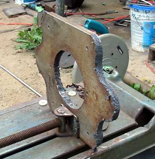
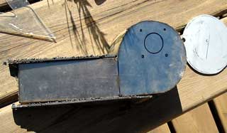
| A cleft over hunk of pipe cut off
off of the pedestal pipe was cut to be a 3/4 round, then plates welded to
the ends and top made the enclosure. The photo left shows a
never-to-be-seen-without-an-endoscope view of the inside of the box. Once
ground smooth, it really looks fine. Can't wait until the polishing starts
on that!
|
|

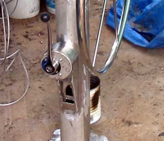
Occasionally I would step back, or look from above ( photo left ) to make sure nothing horrible was happening. It may be out but 1/4" here or 1/8" there but as long as it looks even and proportional, it doesn't matter. This is something one learns while doing the interior. Because of curves and angles assisting optical illusions, it's sometimes better to purposely knock things out a bit so the eye perceives it as it should be, even though it isn't aligned at all. |
|
|
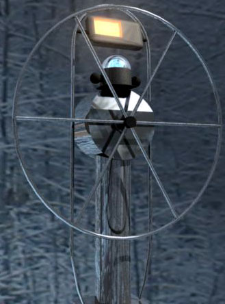
The bar across the top is to support the display
unit ( I have yet to build ) which is going to be about 2.5" thick but
needs to be angled toward the viewer. This is why it is sunken forward
instead of straight across. The hooks ( which will have rubber balls pushed
over them when not in use ) will be used in tandem with the small "U"
below for a cockpit table. Having a table in the cockpit while at anchor is
a wonderful experience to eat at. We wouldn't be without it! What's Next: The cables will be connected up and the unit mounted. Over winter I will build the display unit. That will be listed here.** |
||
![]()
to Individual projects main page