| Project 53 |  |
Pedestal Display Dash Unit |
Assuming you've already had a look at pro52.htm, the sender unit, even while still on the drawing board, has already offered some challenges. The style of bus to use is the #1 question. The old screw style terminals are good for positive connection, but can be difficult to deal with unless a substantial size. Plus they are completely exposed unless mounted in side their own little box. The electronic part of the sender has been pretty easy thus far as I am avoiding any difficulties by using methods I am familiar with. Integrating other systems into this unit (i.e. the dashboard PWM Dimmer/ rudder indicator/ remote steering controls ) has been hard to resist. I can only use the "safety in numbers" theory to keep them individual units. That way, if one fails, it's not a major nightmare to fix, nor a crisis.
There isn't much in the way of diagrams to show as most of them are scribbled (unintelligibly) on the backs of cigarette packages, but I can explain the general input types, and considerations. KISS. I am writing this page also for myself, to keep things in perspective.
| General input types: | |
| Analogue | The analogue inputs
vary greatly, as do all data acquisition setups. Each input should be
tailored specifically, but keeping a global flexibility is favorable. A specific example would be the rudder angle input, which must be also fed separately to the dash indicator. This being an analogue signal from a 2k potentiometer attached to the rudder, should be straight forward as an analogue input to a PIC microcontroller. Problem is, the auto pilot also uses this pot, but may not always be on. The solution is to "power share" to the pot via rectifiers from both sources. Unfortunately, the autopilot also draws on the circuit from the pot's center pin, on or off, so this must be calibrated out logically. The analogue input from a thermistor to indicate temperature must have a controllable gain amplifier, as well as an offset, if that analogue input were to be used for anything else. Engine gauges have voltages driving them ( in some cases ) so the analogue input must track the voltage without altering it. This again requires an amplifier, but with perhaps more/less gain. I'd like everything to match the hypothesized max/min levels, but I have learned from past experiences that "the great unknown" ( because none of these data are available in this day of mass knockoffs and "non-standard-standards) can, and usually does, go far beyond what you'd expect either large or minute. Analogue?? |
| Digital | Digital, which I like a lot,
can be described as anything logical and predictable, hence the
aforementioned reason for my fondness of it.
NMEA input from the GPS, or depth sounder, is
digital. It doesn't change, It's always predictable within it's
pre-defined parameters. NMEA in some cases is also bi-directional. It is
close enough to RS-232 to call it RS-232. It's in standard
ASCII so very simple to monitor and write software for. Pretty much all of the digital here is a serial stream, with the exception of switch state monitoring. Other digital inputs are likely going to be from stuff I have already built, like the rudder indicator, if I go that route, the digital barometer chip, the ham radio control head, switch state monitors, and onboard stuff. Digital outputs may include an NMEA repeat to RS-232 for the dash PC, control relays for lighting...whatever. The interface to the pedestal unit (pro52.htm) is, of course, digital. It will be a bi-directional MIDI style interface going, perhaps a little faster the 32kbps as it's going through an IEEE CAT-5 cable, and is in my own format...if I so choose, although sticking to ASCII like NMEA does might be a good idea for troubleshooting. |
| October 4th 2008
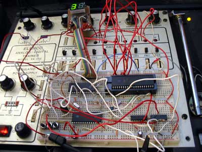
The board ( shown in top of page
picture) came out fine the second try, done on the boat at around room
temperature. The first was ruined because it was too cold perhaps, not
sure. Photo-etching at anchor can be tricky lol! Another change is the Rudder
Indicator. It now sends a data/clock serial signal with position and dash
dimmer CDS info, so no need for an ADC there. The ADC, an MCP3208, has 8 channels at 12 bits. It's fast enough and uses a serial bus, so ideal for the situation at hand. 12 bits gives far better resolution than 8 bit, the original chip slated for this job. 256 to 4096, not bad! For most of the apps, save the barometer, the lower 4 bits will get chopped, but nice to have anyway. The EEPROM is of the 256K variety for now, but I'm trying to decide if this is enough for logging more just than barometric trends, say depth/sec or wind/sec. If the pedestal PC is off, what do I want to be able to log? At 1 byte/second it'd be rolling over in 3 days. A large (64 megaBIT...) serial flash could be used, but the speed/program space/ram overhead on arranging sectors and managing blocks (whatever) is so high. All the same, 8 inputs at 1 byte/second could go for 11 days. |
|
| The NMEA PIC's
(& projects) have proven to be a challenge, and have their own page
pro59.htm as that would make this
page too huge! Now they "spirt" data on to the bus, waiting only if the
bus is tied up by another NMEA PIC. This sounds hap-hazard, but works well
and frees up the DashPIC even more. If the DashPIC wants more data, it
will poll more often. NMEA sentences are by no means a constant stream
anyway. 1 per second is the norm it seems.
|
|
| The tests are promising on the
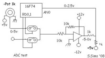
16F74's ADC inputs. I wrote some code for the ADC input 0 (pin2) just to
check it out, called ADC1674.asm. The code also
switches RD,0 and RD,1 back and forth to control a 4066 to switch from one
analogue input to another. The delay there is less than 6uS, but the
op-amps is much higher, 40uS passes before it is totally stable.
All this means is the desired input will need to be switched in after the last sample was processed, but before any other routine that will tie up the pointer...i.e. checking NMEA input :) The (+) and (-) 12 volts will actually be more like +/- 8 volts, or like the schematic so far says, 5.6 volts. For my tests I tied the (+) in on the op-amp to ground. this turned the 0-5v input into -5 to 0, or, after the resistor ladder it reads 0 to 2.5 volts. In the final design, there is a pot there instead to control the positional offset. If there were 5 volts there, the range would be 2.5 volts to 5 volts. Also the 10k feedback on the op-amp will be a pot for controlling the gain.
I assembled everything on the wish-box for both the NMEA stuff and the ADC stuff, which is mostly on the right side. The NMEA stuff is still there only because I think it's cool to display the time off of a GPS that is plugged into a USB socket, then converted to a virtual RS-232 port, COM4, then routed through the "Free Virtual Serial Ports Emulator" (google it!) to virtual multi-output COM5, down through to the real COM1, out to the NMEA PIC then encoded into my own "S-BUS" chaos code for the 2nd PIC posing as the DashPIC and displaying it on an LED display. Anyway, he he, here's how the pulse after the LM-324 Op-Amp looks. Pretty slow, but hey who's in a rush? We're sailors! As I mentioned before, the 4066 output (inset) is fast. Sorry about all the noise on the line. There just isn't a lot of ground on these wish boards is there? I have no electrolytics to filter + I'm surrounded by "AC everything" at the moment which isn't helping either. One good thing about having a shop on a boat, no AC!
|
|
| March18, 2009 During the last week I managed to do some tests while we were on the boat. The NMEA (high speed/coded) needed fixing. It was mostly to do with timing. Also the NMEA code $0D needed to be removed from the NMEApic's as it was causing inadvertant carriage return situations, thus no data was following. $0D is, of course, the wind speed and direction. The one I really need for the simple auto-pilot routines! It is now code $16 instead. ($0D) is GPXXX if a car. ret is needed for whatever) The main NMEA routine is now in dashPIC.asm (always up-to-date) The multiple NMEA signals didn't appear to cause a traffic jam on the 2 wire bus to the PIC17F74, but I'm sure there were a few collisions. Thanks to CRC's though none got through to the display the whole time I was testing it. The "spirt" system seems to work quite well! |
|
| The Pedistal Original display
was connected directly (via RS232) to the dashpic for monitoring, and
modified to accept the $$ headers just to try it out. I chose the wind
NMEA to display as there was a storm that night! The video is on youtube.com, but can be seen here --->> The compass underlay is to see true wind direction as the plate will be showing heading and the "Windex" will be showing the wind relative to it. Because I couldn't hook up the compass (need cable yet!) I couldn't show it. The alternate (#5) NMEA input was tested and performed as expected, but can only be used as an override, i.e. DGPS will override Furuno GPS. While the Alternate has signal, the other is ignored unless there is a space between sends.(>8 seconds, which could be modified to, say, 1 second) in which case the original input will have control again. This was done because when the dash PC is on, the Fugawi program sends Zenstar USB DGPS data to the comPort, which is more accurate but more power consumption. The difference is noted by setting bit 6 in the NMEA PICs type header code. Other parts were tested as well, but before I could test the WindGen, Solar and waterGen charge Amps inputs and the "real" Ruddim inputs we had to go back to Alberta.
|
|
| The external 3208
serial 12bit ADC works fine, and was very easy to program for.
ADCxUSART1674.asm is the asm/text file if
you want to have a look. This routine takes each of the 8 12 bit
inputs, converts them to 2 digit ascii hex, then outputs them to the USART
which is set to 38,400 baud. This way it's easy to monitor with hyperterm
in windows or any comport style program. I wrote a little flash routine to
display them but am not going to bother posting it as eterlogic VSPE for
TCP communication with flash. To get a really good idea of how the data acquisition box (dashPic) program is being set up, see the flash flow chart in boatwiring-web.zip or online at dashPicFlow1.html . (Warning, the zip file is almost 32 megs now!) |
|
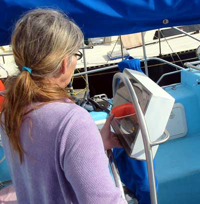
| Here's Gena holding the
somewhat bulky pedistal PC display and control box in the binnacle. It
*is* rather large, but we'll see if we can get used to it. The reason it
is so thick is because the red LEDs need to shine onto the transreflective
display at night.
It took a couple of afternoons (as I have never programmed a PIC for EEPROMs before) and I was able to enter characters using hyperterm, through the USART, then have them display back, even after cutting the power to the wish board. Yay!! It's pretty cool to be able to do this. |
 |
| I won't
show the boring scope displays for timing, but really it wasn't that hard.
Sorta like the I2C bus on the stereo, with timing considerations. The main flowchart had to be changed as the write cycle ties up the EEPROM for a whopping 3 - 5mS, forever in microprocessor time! To further complicate things, the test for checking the status, i.e. is it ready for another load of byte/page? involves sending another command as if one were going to write, then checking the flag returned. Problem is, the address in the command must be the same or it won't work! So that means keeping 2 buffers tied up with the address. Even worse, it won't work with the upper half of the EEPROM addressable by a flag in the actual command bytes, or that changes something or other to yield "don't know" data. DUH! My solution is to take the absolute max programming time 5mS (usually 3mS) and just use one of the TMR modules in the PIC 16F74 to handle the "availability" stautus of the EEPROM. 400 khz clock rate is also VERY slow, but hey that's amouré. |
|
 |
|||
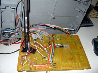
| Finally the hardware is beginning to take shape. The photo (right) is the back of the board. Notice all of the wiring comes in from behind. It took me a long time to realize that doing this keeps the top of the board clear for chip switching, adjustments etc. It all comes to a single point in the corner so board can be easily tilted out. |
 |
||
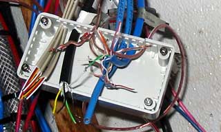
| This photo shows board snapped
into place. Having the ideal box really helps. It pays to look for surplus
boxs. Just rip their board out and put yours in!
The photo below left is the lower half of the connection box. It's hard to see, but the upper lip has been filed to accept the ribbon cable. Getting all of those wires squashed down to close the box may be difficult, but it's compact. The photo to lower right shows the position of an RS-232 radio-modem (vertical on the end) that will display some NMEA data on a handheld remote as well as control some things such as steering, windlass, horn etc. That will be covered below... |
 |
||
 |
 |
||
|
|||
Eventually, all of this will come together. Stay tuned!
![]()
to Individual projects main page