| Day 428 |
 |
Tub Enclosure/ Rudder
Sensor |
| The big day has arrived! The
heavy vinyl flooring is going in...as a tub enclosure! First we had to
do a trial fit, better now than after the silicone is on. We learned
that elsewhere if I recall correctly, maybe on the house.
|
|
 |
The job required us both is any case. Gena
called me away from my "oh-so-important" job forward, and then quickly
asked " ok, so how should we do this?" referring to the method of
actually mounting the thing. I just looked blank-faced and rattled
something off so as not to look stupid, forget what, and away we went. I
don't recall really because the main thing on both of our minds was to
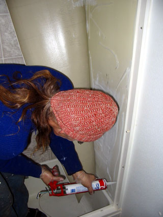
get air! Running a bead of silicone here and there seems pretty benign ventilation-wise, just the occasional acidicly annoying whiff of the stuff. But pump out three tubes of it in an enclosed area over 2 minutes, and it's a WHOLE different story! Even now days later, just writing this, I can still smell it. Honest! I grasped for the door passing Gena, "It's your turn!" on my way to anywhere without the stench of that stuff hanging in the air. I opened up hatches, even though it was still -20ºC outside, pened anything that would open, started the vacuum cleaner with the hose sucking air outside. "OMG! They're going to find us in spring, stuck to the bath tub walls with silicone, dead!" I kept thinking. We pressed and squeezed bubbles out and flattened and rolled for a while after we re-gained our air, then voila! An enclosure that looks way better than before! ( Photo below, notice the angelic aura around the inset-imagine angels singing etc. I'm sure I heard them...silicone inhalation is a weird trip man! ) |
|
|
|
| After a well deserved break,
we went back to our previous project plans before the "tub-bug" got us.
|
|
| Gena welded together a most fancy
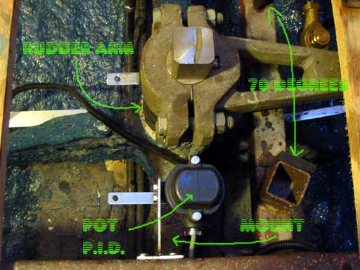
S.S. bracket to attach the "rudder sensor", or, " PID". (That's what Furuno
calls it, I just call it a "pot", short for potentiometer. Of course if I
was going to sell a pot for that much, I guess I'd have to call it
something else too! ) PID is "Position Indicating Device", but then POT
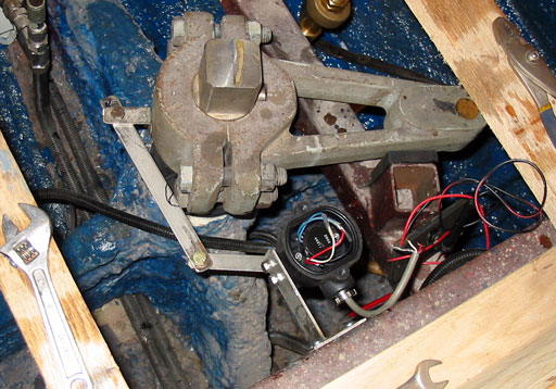
could stand for "Position Of Tiller" lol. My image/word overlay shows the basic outlay of the system. The idea of it is to send rudder position "data" to the steering stations and auto-pilot setup. This is so the pilot knows where the rudder is at all times, and the "real" pilot too! Trick was, how to mount a sensitive little thing like that to a giant thing like the rudder shaft. Gena, in all her wisdom ( and my suggestions: take it or leave it ) added a bracket tapped and screwed into the rudder arm ( "quadrant" in cable steering circles ) that is exactly the same radius distance from the center of the rudder shaft as from the center of the pot shaft. Gena measured correctly as the two swing in perfect unison. It's cool to watch it go! You may be witnessing the first-ever internet photo posting of this mysterious device. I hope I haven't broken any laws. I hope this is the way it is supposed to go. In the side view photo ( right ) Gena's home made rudder seal can be seen. It was made from a chunk of tire inner-tubing. Not directly though. It needed to be conical in shape. A cone cut-away was cut, then wrapped around and glued with special tire glue. The clamps aren't on it yet, but looks like it may just work. It's one heck of a lot cheaper than that latex sheeting they sell for this purpose. ( Don't even bother if you want a deal because it's WAY more than a whole box of latex gloves! Go figure.) |
  |
||
| The top of this tube is far above the water line but it is still needed to stop spitting of water during rough conditions (I guess) and is required. The view in the photo below shows the connecting arm in place. Notice the black felt pen marking? | |||
| That needs to be cut out
because the bolt is hitting when hard over to port. Ok ok one little
mistake! The top of the POT has been opened to show the internal wiring. The auto pilot (in the original " non-Sandy & Gena" mode) supplies the 5 volts and ground to it. As the rudder turns, the voltage from -35º to +35º (70º total) goes from exactly 2.0 volts to exactly 3.0 volts. What a coincidence! The only problem is we want the position displayed without the autopilot guzzling our valued battery juice. After several other proposed solutions by me, "we" have finally come to an appropriate one. |
 |
||
| This paragraph gets a little
"technical" so if that's not your bag, then just skip off this grayed area.
Because we require that 3 displays be running
off of this POT, a little electronic ingenuity was required. If one powered
the POT from another source, the autopilot would do fine, but the
autopilot circuitry itself varies the voltage slightly. It also adds a bit
of pull-down when turned off. This is only a 2k pot after all. Slight
variance could mean big problems! Solution: insert an operational amplifier (op-amp) inline, configured as a follower or non-inverting amp, and use it to drive everything. You can't beat pure amps for driving power! Then use the 5 volts at the rudder indicator to power the pot. For more on the rudder indicator, click here. The project is also accessible from projects main and will be updated by Feb 2008. |
|||
|
|
|||
| Back to the wood work
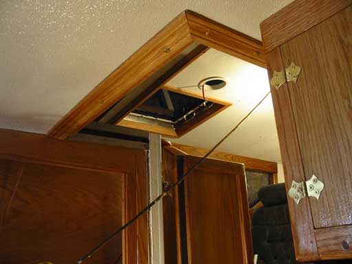
I go! Another nagging eyesore has been the entrances ( gangways) into the boat, and down below. I finished the frames and screwed them in place with a dab of silicone for good luck. ( Plugging my nose of course!) Anywhere screws go into steel frames, silicone is added in the mix in an attempt to stop rusting. |
|
I bought some of those
plastic Robertson screw covers and painted them carefully with acrylic
paints to look sorta like wood grain. ( They never match anything but raw
pine!) They blend in well don't you think? :) |
 |

Day 428:
10 hours total: Put in vinyl floor tub surround, mounted rudder "POT", mounted
ceiling trim over entries.
PS, check out
projects main for lots of new/updated entries!
(Jan2008)
| TO Replace
this button with a link to your site, mailme back..to Main page Sail1.htm |