|
Pedistal PIC II |
 |
Tests and Construction |
|
Pedistal PIC II |
|
Tests and Construction |
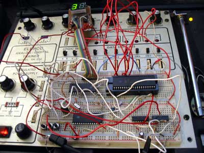
| After that rather involved start page, and
some intense rambling, I am pleased to announce the actual physical
construction is under way. With some minor design changes the keypad idea/design seems to be working as expected. As shown in the above picture, the layout of the cap/ind. pads was changed. I realized that a finger may inadvertently touch the enter on the way top the up arrow as they are all so close. Also I have added some orange SMD LEDS to the "keypad" so they will illuminate at night a little. The minor design change was to the oscillators. They were "cross talking" and getting into the mix no matter what I did! So the solution was to turn them on one at a time. They are still individually tunable and respond very quickly. I have been strobing them at 1/10 second. I did have some problems tuning the PIC Xtal to come within a Khz or so of the other oscillators. If I had to do it again I would just make a separate colpitts for it as well. I stopped after being satisfied with the key pad results, and will resume after I complete 2 less intense projects, the rudder/dimmer and the Pic stereo. By then the Christmas rush will be over and things can get more "down to business"
|
| Also, as an
addendum to the previous page, I found a way to save to the hard drive.
Use a "SharedObject" to write to the HD! The only limitation is size.
This can be changed in the host machine to infinity, and doesn't need to
be changed again. The default is 100k and is a security measure to make
sure malicious coders don't write a routine that fills your HD with
junk.
|
|
BYE BYE MIDI!! |
|
| Update: November
20,2008 After all the monkeying I have been doing with the MIDI interface, and the code/delays it creates, not to mention buying the hardware, I have actually found a way to interface an RS-232 Com Port with Macromedia flash! Actually, I found 2 ways. The first one I found
seemed tempting at first. It's called SWFkit pro, and basically is a
"wrapper" to embed the flash program inside of that has cools add-ons like
Com port access, and the code to deal with it in it's extended .as class
library. After an hour or so, I had it working. The trial version had a nag
screen at the start that you must click to get rid of, plus a ...this is
a...trial version in the center of the screen. OK I thought, I'll just buy
the thing! After a few hours of despair, I started checking out "bizarre" methods, being naive and full of hope as I am first thing in the morning, and I discovered that Flashes XML communication, could talk to the new Freeware Virtual Ports Emulator's (by Eterlogic, I could kiss those guys! I think I will!) TCP port! That means the data can pass back and forth via XML>VPE>Com1>pedPic. The software connection worked well, but I had to actually hook something to it. |
|
| An NMEA PIC I have just finished
was set up to receive the data at 4800 baud, then that data is pumped at
high speed into a main DashPic development chip I've done to test the data
transfer rates etc. That was rigged to output the data to a 7 segment LED
display. I then loaded an NMEA sentence from the GPS on the boat (I recorded into a text file) into the Flash program, fired it up and presto!! Out it came! Yay! This will totally work, but the data the Flash program is receiving must be terminated with a "zero byte". That means binary 00000000, not ascii '0'. It's because of the TCP to XML in Flash. I suppose a <cr> would have been too antique lol! Because it can be set to any IP address, I can't see why it couldn't be interfaced with the internet to another computer as a client. Pretty cool that. |
|
| I can't wait to post
this on the electronics forum. I know there are tons of people out there
looking for a way to do this. Not needing to encode everything into 7-bit
MIDI format at a ratio of 6:1 bytes is a relief. Now I can continue.... ...just need to buy yet another USB-RS232 dongle. |
|
|
PROGRESS |
|
| Here's a little
update that was hinted at above: The NMEA PICs have been completed, with dual inputs, more on that on pro59.htm , and some ADC testing for the "DashPic" as I have dubbed it, here on pro53.htm . Sorry about all of the links, it's just such a huge project! Once everything is done, tested, and forgotten, I'll put the "history" on to a separate page, and the completed project on these pages. Next is to continue with the programming of the PedPic now I know what I'll be using for hardware to software interface. |
|
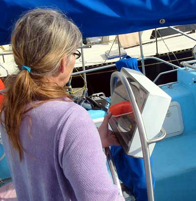
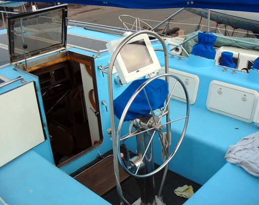
| Here's Gena holding the somewhat
bulky pedistal PC display and control box in the binnacle. It *is* rather
large, but we'll see if we can get used to it. The reason it is so thick is
because the red LEDs need to shine onto the Trans reflective display at
night. I found a bolt on style tractor tire nipple at a local tire shop in Thorsby, only $5 ! and it is perfect to add that bit of PSI to the box. The plugs have also arrived. The reason 2 plugs are being used is because I have decided to add this PC to the Ethernet hub inside the boat. That way, using "tight VNC" a virtual desktop server/client program, we will be able to bring up the pedestal display on any PC in the boat, and vise- versa. Pretty cool stuff hey??
|
 |
|
Big Changes.... May 8th 2009 |
||||
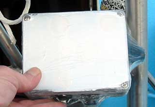
| Unfortunately, or fortunately depending on how
one looks at it, I had to shrink the case. It was just too big and ugly, so
I've cut the box down just big enough to fit the tablet PC inside, and the
temp/pressure sensors on a little board. A red plastic bezel must be snapped
on for night use, although the display can still dim down automatically.
Seems to work. Because the keypad board is so large, I had to change the entire keypad style to piezo switches. This is the same kind of circuitry I used in the design of my V-Drums. It's a little upsetting, but they do work well (see flash below) and the little box I put them in is sealable. I will still coat all of the circuit boards inside ( the video-USB, the PedPic, & the RS-232) just in case moisture enters. |
 |
|||
 |
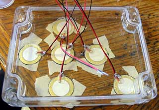
The little "waterproof" case I bought from
Digikey has a transparent lid, good for backlighting the keys at night. I
recessed the 20mm piezos in by their thickness, being careful to line up a
further depth for the little factory solder points with the Dremel router
mount. *When routing plastic like this, mind the speed or the plastic will
melt! After test fitting, I drilled small holes through for wires then glued each one in with silicone and held down with tape. |
|||
 |
|
|||
|
||||
 |
 |
|||
| The small board with connecter
strip mounted is shown above. The round disk is the valve to fill case with
air. A printer style plug has been sealed under 2 layers of Goop, for
strength, then silicone for a seal. It should hold under a couple of lbs of
pressure! If not, then a bead of butyl calk (marine) will certainly keep it
sealed. The rim gasket hasn't been done yet, and I ran out of time to do it.
This will need to wait until we are underway pretty much! |
 |
|||
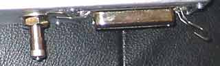 |
The clamps (photos above this)
were made (painstakingly, as no tools now!!) of 1/2" stainless bar leftovers
from chainplates. I partially ground them out so I could get the mounting
holes drilled & tapped, then cored out the centers so they'd line up.
Once cut apart, the clamp bolt holes were expanded to 1/4" and the brackets
threaded. As can bee seen, one clamp is already doing the job! After the photo I ended up carving out a little more for a closer fit. |
|||
 Much better! Doesn't block compass or corner rails. |
||||
| **More to come! As most of the previous keypad design info & the layout itself has been changed, these pages will be pulled and linked to from the proper, more organized project page! I won't do that until the project is "stable" he he! Cheers! | ||||
to pedistal part1 |
|
...to dashPic sender |